ULtra Compact 1800W charger + Eltek programming

Ohbse said:
That is some absolutely awesome work Remmie! Thank you so much for your efforts and sharing with the community.

You're currently working with a single rectifier, do you think anything fundamental needs to change to drive a pair of rectifiers connected in series with a pre-configured total target voltage? I'm thinking 28s lithium packs such as Zero etc.

I think this would be an ideal onboard charging solution for many electric vehicles, either a single rectifier up to 60v or two for 120v - that covers an enormous range of battery configurations with unbeatable power density and reliability.

No fundamental change is for series connection is needed, because that's exactly what I did already. :D
I have some threads on the electric motorcycle forum about my DIY charger for my Zero.

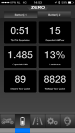
I use 1 flatpack S and 3 flatpack 2HE to get a 9.1 kW DIY charger :shock: (onboard 1300 Watt + 1800 Watt for the flatpack S + 3x 2000 Watt for the Flatpack2 HE's) this gives 9.1 kW of charging power with very high efficiency (95-96%). It weighs about 8 kilo's and fit's into a tank bag.

Some pictures and more info in the electric motorcycle forum :

http://electricmotorcycleforum.com/boards/index.php?topic=5763

I can also separate the 4 flatpacks into 2 separate chargers. That way the weight is greatly reduced.
The charger then consists of 1 flatpack S (1800 W) and 1 Flatpack 2HE (2000 W). Together with the onboard charger (1300W) it can charge at 5.1 kW using a type 2 mennekes plug and EV-charge point.
Now with the current control on the flatpack I can also take full advantage of a domestic outlet with 16A 230V single phase.

If I set the charge current on the flatpack to 20A it draws about 2200 Watt. The onboard charger draws about 1300 W to give a total of 3500 Watt (is 15.9 Amps at 220 Volts, 220 Volts to allow some voltage sag on the cabling etc). So far I can charge more than 1 hour on a 16A circuit which even has other appliances on it (fridge, lights etc.) without the breaker tripping.

IMG_1743.jpg

IMG_1748.jpg

image.png
 
So Remmie, can you confirm the exact procedure to do to be able to set the flatpack S at teh desired voltage and current permanently?

and can you post the circuit that you built to monitor and or modify these settings?.. :D

I have two flatpack S thata re waiting for that. While waiting for that i am destroying their amazing efficiency with the need of my 3 stack of 1200W boost converter to get my desired voltage..

thnaks!

Doc
 
That's a very nice dry weather charge rig!

Thank you so kindly for your excellent work reverse engineering those nice power supplies!
 
Doctorbass said:
So Remmie, can you confirm the exact procedure to do to be able to set the flatpack S at teh desired voltage and current permanently?

The procedure for permanent default voltage change is :
You have to have a connection to the CAN-bus (obviously)
if the serial number of your unit is 123456789012

send 0x05004804 0x12 0x34 0x56 0x78 0x90 0x12 0x00 0x00 (to log in to the rectifier)
send 0x05009C00 0x29 0x15 0x00 0x80 0x16 (to set the permanent default voltage) EDITED !!!!!

After about 10 seconds or so the output voltage should change to the new default voltage.
Now wait 30 seconds and disconnect the power to the rectifier.
When you start up again the voltage will default to (in the example) 57.5 Volt. The default voltage is determined by the last 2 bytes of the second command. Multiply your desired voltage with 100 (57.50 => 5750). Convert this number to HEX values (5700 => 0x1680). switch the two bytes (0x1680 => 0x80 0x16) and you have your code for setting the voltage

For permanent current setting I have no procedure.
It could very well be a command similar as to change the permanent voltage but I have no knowledge about that. I also have no "spare" Flatpack to experiment with.

In my post above (with the latest arduino code) I respond to the rectifier's questions which is the elegant way of communicating
I [strike]THINK[/strike] confirmed that it is also possible to just send the current and voltage command every few seconds and that the rectifier understands it and acts accordingly, but you have to keep sending those 2 messages otherwise the rectifier defaults to his default output voltage and maximum current.

To set the current control (and also voltage) message
Send the following 2 messages at least every 10 seconds (5 or less seconds may be better)
if the serial number of your unit is 123456789012

send 0x05004804 0x12 0x34 0x56 0x78 0x90 0x12 0x00 0x00 (to log in to the rectifier)
send 0x05FF4004 0x64 0x00 0x80 0x16 0x80 0x16 0x3E 0x17 (to set the current, the voltage and the over voltage protection)

Current is the first two bytes of the second message (0x64 0x00). Switch the 2 bytes (=> 0x00 0x64 = 0x0064). convert to decimal (0x0064 => 100). divide by 10 (not 100) and you get 10.0 Amps.
If you would want 28.6 Amps you invert the procedure : multiply by 10 (= 286), convert to HEX (0x011E), switch first and second byte (0x1E 0x01) and you have your desired current.
The voltage is the 3rd and 4th byte of the second message (same procedure but division/multiplication by 100). 0x80 0x16 would give 57.50 Volts
The 5th and 6th byte should be the same as the 3rd and 4th byte respectively (so also 0x80 0x16)
The 7th and 8th byte are the over voltage protection limit. With 17 and 3E in the example it is set at 59.50 Volts (same calculation as output voltage)

For the circuit I used a buildcircuit LCD DIY Kit together with a 5V CAN-bus board and a 75V to 5V DCDC converter to power the circuit.
http://www.mikroe.com/click/can-spi-5v/
http://www.buildcircuit.com/serial-lcd-do-it-yourselfdiy-kit/

Easiest would be to use an arduino UNO with a CANbus shield, but that ends up a little bulky. You would have a super compact high power rectifier and a CANbus controller half the size of 1 flatpack S :D
I'm now looking into finding a very small microcontroller board with CAN-bus interface and see if I can fit it inside the Flatpack S. That would be the ultimate solution. Either that or find the command for permanent current limit change :wink:

maybe this one is worth looking into. it looks quite small
http://www.hobbytronics.co.uk/leonardo-canbus

!!!! a word of caution when you use multiple flatpacks in series!!!. The Can-bus is referenced to the negative DC output. So you cannot connect to both can-busses of two flatpacks in series or you will destroy the canbus controller on the flatpack. But for current control that is not necessary. Only connect 1 flatpack to the can-bus and that rectifier will determine the current. the other will follow) obviously
 
remmie1972 said:
Current is the first two bytes of the second message (0x64 0x00). Switch the 2 bytes (=> 0x00 0x64 = 0x0064). convert to decimal (0x0064 => 100). divide by 10 (not 100) and you get 10.0 Amps.
If you would want 28.6 Amps you invert the procedure : multiply by 10 (= 286), convert to HEX (0x011E), switch first and second byte (0x1E 0x01) and you have your desired current.
The voltage is the 3rd and 4th byte of the second message (same procedure but division/multiplication by 100). 0x80 0x16 would give 57.50 Volts
The 5th and 6th byte should be the same as the 3rd and 4th byte respectively (so also 0x80 0x16)
The 7th and 8th byte are the over voltage protection limit. With 17 and 3E in the example it is set at 59.50 Volts (same calculation as output voltage)
y

This is so awesome Remmie, What surprised me about this is that you ACTUALLY SET A CURRENT LIMIT. I fiugred you conctrolled it through the code.
 
grindz145 said:
This is so awesome Remmie, What surprised me about this is that you ACTUALLY SET A CURRENT LIMIT. I fiugred you conctrolled it through the code.

Yes, that's indeed very handy and works pretty good.

I'll try to see if I can change the code to just send the 2 commands for logging in and current control every 2 seconds is sufficient for current control. That way the code is really really short and efficient.
That would also help the search for a small single board CAN-bus capable microcontroller board that can execute this. Almost every such board has an example program to send a CANbus command and repeat that. Changing that command and adding a second command would be peanuts. That way we're not stuck with just arduino which is an excellent and cheap development tool but for this purpose too bulky.
 
Thanks Remmie, that is very interesting information.

Have you figured out a way for charger to switch off or disable the output when timed out (CAN comm lost)? That looks quite important to avoid accidents. Or course you can set default voltage very low, but still not a very elegant solution.
 
Thanks you very much remmie! that is exactly what we need! you are AWSOME!

Doc
 
Good news !

I can confirm that just sending the 2 messages from the previous post every few seconds is enough to keep the rectifier logged in and keeping the set current limit.

I started with 2 seconds interval which worked fine. 10 second intervals were also fine. 15 seconds proved to be too long :lol:

This makes it very easy to make a microcontroller with CANbus interface and program it with just those 2 commands and a 5 second loop
I think this board may be a very good oppertunity.

leonardo-canbus-6-500x500.jpg


http://www.hobbytronics.co.uk/leonardo-canbus

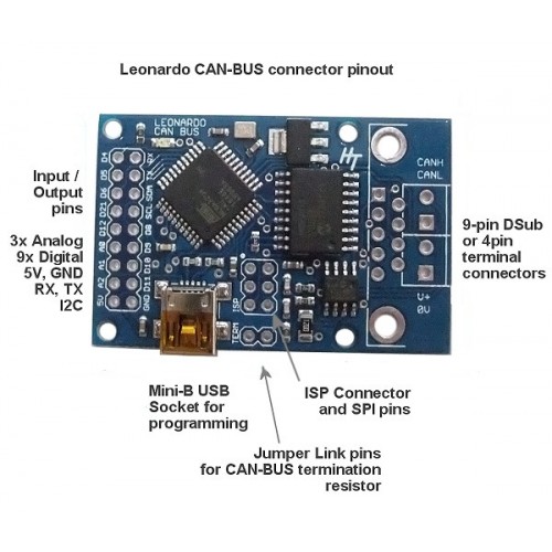
It has a 12 to 5V converter, arduino compatible microcontroller with bootloader, CAN-bus interface and a mini USB connection for programming.

The Flatpack S uses a 12 Volt Fan with 4 wires to keep itself cool. The Fan is powered by a continous 12V supply and uses a third wire to set the speed. I think the fourth wire is for speed detection but that's not important. The 12V supply for the fan can be used to power this microcontroller board (because it has the 12 to 5V converter). I just have to check whether the negative of the fan is the compatible with the negative of the can-bus.

There is also some small room next to the Fan of the Flatpack S (in the housing) to place that little board.
The full size of the board is 51x33mm but it looks like you can cut of the connectors on both sides (DB9 and header) to end up with something like 33x33 mm. That would fit perfect inside the Flatpack S.
The can bus connection points are in the back of the unit (the fan is in the front) but a small twisted pair wire, protected by shrinksleeve can be run from front to back to the little board.

That way the microcontroller board keeps setting the voltage and the current and you wouldn't see it because it is inside the Flatpack.
Thinking further you can put potmeters or pushbuttons on the microcontroller board to set the voltage or the current on the fly.

I think i'm going to order a board and maybe a small oled display as well to see if it works and if it fits inside the flatpack S.

for reference : this is the code i used to test. As you can see only a few commands. It has no detection of the correct serial number so you would have to change the first command according to your serial number and of course the second command to your need for current and voltage. If anyone is interested I can cook up some code with which you could easily input voltage and current somewhere in the code. The rest of the code would then have serial number detection and the necessary commands to set the voltage and the current. Basically a slimmed down version of my code with the LCD, just without the LCD :lol:

Code:
#include <mcp_can.h>
#include <mcp_can_dfs.h>
#include <SPI.h>

MCP_CAN CAN(10);                                                        // pin for CAN could also be 9 or other

void setup()                                                                  // Initialisation routine
{CAN.begin(CAN_125KBPS);}                                          // set canbus speed to 125 kbps

void loop()                                                                   // main program (LOOP)
{
unsigned char stmp1[8] = {0x14, 0x14, 0x71, 0x11, 0x08, 0x20, 0x00, 0x00};    //this is the serial number of the flatpack followed by two 00 bytes 
CAN.sendMsgBuf(0x05004804, 1, 8, stmp1);                                      //send message to log in
unsigned char stmp2[8] = {0xA0, 0x00, 0x80, 0x16, 0x80, 0x16, 0x3E, 0x17};    //set rectifier to 16.0 amps (00 A0) 57.60 (16 80) and OVP to 59.5V (17 3E)
CAN.sendMsgBuf(0x05FF4004, 1, 8, stmp2); 
delay(2000);                                                                  //2 second delay 
}

If the microcontroller loses connection to the rectifier, the rectifier WILL default to maximum current and default voltage. So like "circuit" said. Maybe it is best to program the rectifier to set the defaultoutput voltage to the minimum possible (43.5 Volts) and use the microcontroller board to set desired current and voltage.
 
I've gotten the Leonardo CANBUS board board in the mail today.

It's nice and small and the connectors are packaged seperately like they say on the website. Very Flatpackfriendly :D

This is how to connect it to the flatpack :
1. solder a twisted pair to the CANL and CANH solder pads on the right side of the board. There are screw terminals supplied in the kit but to keep the board low profile I chose to solder the CAN wires directly onto the board.
2. make a bridge on the TERM solder connections to terminate the RS-485 with 120 Ohms. The 2 TERM solder pads are on the mini-USB side of the board.
3. connect the other side of the can bus wires to the canbus on the flatpack
3. Install the arduino software (available for free from Arduino.cc)
4. Connect the leonardo CANbus board with a USB to mini-USB cable
5. Copy paste the code into a (arduino) sketch.
5a. At the top of the sketch there a 5 lines of code to set the : current limit, output voltage, overprotection voltage,5 or 60 seconds walk-in and the step the current limit takes as you push a pushbutton connected to D11 and GND. Change these as you see fit.
6. Select the appropriate settings in the arduino program (board : leonardo)
7. activate the serial monitor at 115200 baud in the arduino program
8. hit the upload button (to upload the code into the can board)
9. The LED on the board lights up every time a message is received or transmitted
10. The serial monitor shows all received and transmitted data and gives an explanation of what is sent or received
11. build the board into the flatpack
12. enjoy a adjustable voltage (43.5 - 57.6 Volt) and adjustable current limited (0-41.7 Amps for the flatpack 2HE, 0-37.5 Amps for the Flatpack S) powersupply
13. if you connect a pushbutton switch to D11 and GND the current is adjustable in steps of 10 Amps

OLED display version to follow :)
Also to follow is whether the 12V from the fan can be used to power the board, this way it can act fully stand-alone, but you can monitor it through the mini-usb. Now it is powered through the usb.

The code is not very optimised but it fits into the leonardo's memory :

Code:
// from rectifier : (requests for logins)
// 05014400 + ser nr + 00 00 from rectifier  : HELLOOW where are you ! rectifier sends 05014400 and 6 bytes serial number and followed by 00 00 (login request)
// 0500xxyy + 1B + ser nr + 00 is send during normal voltage every second. xxyy is the last 2 bytes from the serial number
// after either of these send 05004804 every 5 seconds ! to keep logged in. rectifier does not send login requests so after 10 second the numbers stop until 05014400 is sent
// from rectifier : (status messages)
// 0501400C + status data : walkin and below 43 volts (error) and during walk-out (input voltage low)
// 05014010 + status data : walkin busy 
// 05014004 + status data : normal voltage reached
// 05014008 + status data : current-limiting active

// send TO rectifier (act as controller)
// 05004804 + ser nr + 00 00 from controller : send 05004804 and 6 bytes ser number followed by 00 00 
// 05FF4004 controller sends current and voltage limits (last 4 is 5 sec walk-in, for 60 second walk-in use 05FF4005)
// 05FF4005 controller sends current and voltage limits (last 5 is 60 sec walk-in, for 5 second walk-in use 05FF4004)

#include <mcp_can.h>
#include <mcp_can_dfs.h>
#include <SPI.h>
#include <LiquidCrystal.h>

word maxcurrent = 100;                                                             // set initial maxcurrent (divide by 10)
word outputvoltage = 5750;                                                         // set output voltage to 57.50 Volt (divide by 100)
word overvoltage = 5950;                                                           // set the overvoltage protection limit at 59.50 Volt (divide by 100)
bool longwalkin = HIGH;                                                            // HIGH is for 60 second walk-in, LOW is for 5 second walkin (watch the capitols !)
word currentstep = 100;

/* THIS IS THE MAIN PROGRAM FOR THE LEONARDO CANBUS BOARD
 *  DO NOT ALTER ANY CODE BELOW UNLESS YOU'RE A PROGRAMMER
 */

const int SPI_CS_PIN = 17;                                                          // set the input pin for the CANBUS receiver (on the leonardoboard = 17)
unsigned char len = 0;                                                              // this variable holds the length of the CANBUS message received
unsigned char serialnr[8];                                                          // this variable holds the serialnumber of the Flatpack
int msgreceived;                                                                    // this variable holds the number of messages received
int led = 23;                                                                       // LED output pin for the leonardo CAN board= 23
int buttondown = 10;
int buttonup = 11;

MCP_CAN CAN(SPI_CS_PIN);                                                            // Set CS pin for CANBUS shield
//LiquidCrystal lcd(1, 3, 4, 5, 6, 7, 8);                                              // LiquidCrystal(rs, rw, enable, d4, d5, d6, d7)  or LiquidCrystal(rs, enable, d4, d5, d6, d7) 

void setup()                                                                         // Initialisation routine
{
 pinMode(buttondown, INPUT);                                                                 // Set pin 10 to input (pushbutton for down)
 digitalWrite(buttondown, HIGH);                                                             // activate pull-up on A0
 pinMode(buttonup, INPUT);                                                                 // Set pin 11 to input (pushbutton for up)
 digitalWrite(buttonup, HIGH);                                                             // activate pull-up on A0
 pinMode(led, OUTPUT);                                                               // pin 23 is the output pin for the LEONARDO CANBUS board
 digitalWrite(led, LOW);                                                             // turn the LED of
/*  lcd.begin(16, 2);                                                                // splash screen on LCD
  lcd.print("Flatpack Charger");
  lcd.setCursor(0, 1);
  lcd.print("Made by RHO");
*/  
 Serial.begin(115200);                                                               // Set the baudrate for the seial connection to the PC at 115200
 
 START_INIT:

    if(CAN_OK == CAN.begin(CAN_125KBPS))                                              // init can bus : baudrate = 125k !!
    {
//        lcd.setCursor(0,0);
//        lcd.print("CAN BUS init OK!");

        Serial.println("CAN BUS Shield init ok!");
    }
    else
    {
//        lcd.setCursor(0,0);
//        lcd.print("CAN BUS init Fail");
//        lcd.setCursor(0,1);
//        lcd.print("Init CAN BUS again");
        Serial.println("CAN BUS Shield init fail");
        Serial.println("Init CAN BUS Shield again");
        goto START_INIT;
    }
//    lcd.clear();
}

void loop()                                                                           // main program (LOOP)
  {
    
  unsigned char buf[8] ;
  if(CAN_MSGAVAIL == CAN.checkReceive())                                              // check if data coming
    {
        digitalWrite(led,HIGH);                                                       // turn the LED on
        CAN.readMsgBuf(&len, buf);                                                    // read data,  len: data length, buf: data buf
        INT32U canId = CAN.getCanId();                                                // read the CAN Id
         Serial.println();                                                            // start on a new line
         Serial.print("Received : 0");                                                // leading zero 
         Serial.print(canId,HEX);                                                     // output CAN Id to serial monitor
         Serial.print("\t");                                                          // send Tab
        for(int i = 0; i<len; i++)                                                    // print the data
        {
            if( buf[i] < 0x10){ Serial.print("0");} Serial.print(buf[i],HEX);         // send a leading zero if only one digit
            Serial.print(" ");                                                        // space to seperate bytes
        }
        digitalWrite(led,LOW);                                                        // turn the LED off


    if(canId==0x05014400)                                                             //this is the request from the Flatpack rectifier during walk-in (start-up) or normal operation when no log-in response has been received for a while
       {
         for(int i = 0; i<8; i++)                                                 
         {
           serialnr[i]=buf[i];                                                          // transfer the message buffer to the serial number variable
         } 
          Serial.print("\tSerial Number is : ");
          for(int i = 0; i<6; i++)                                                 // print the data
          {
            if( serialnr[i] < 0x10){ Serial.print("0");} Serial.print(serialnr[i],HEX);      // send a leading zero if only one digit
          }
         digitalWrite(led,HIGH);
         CAN.sendMsgBuf(0x05004804, 1, 8, serialnr);                                  //send message to log in (DO NOT ASSIGN AN ID use 00)
         digitalWrite(led,LOW);
         Serial.println();
         Serial.print("TRANSMIT : 05004804");
         Serial.print("\t");
         for(int i = 0; i<len; i++)                                                 // print the data
           {
             if( serialnr[i] < 0x10){ Serial.print("0");} Serial.print(serialnr[i],HEX);      // send a leading zero if only one digit
             Serial.print(" ");                                                     // space to seperate bytes
           }
       Serial.print("\tLog in with SrNr : ");
        for(int i = 0; i<6; i++)                                                 // print the data
          {
            if( serialnr[i] < 0x10){ Serial.print("0");} Serial.print(serialnr[i],HEX);      // send a leading zero if only one digit
          }
         
         
         msgreceived++;                                                               // increase the variable "msgreceived" 
         unsigned char stmp7[8] = {lowByte(maxcurrent), highByte(maxcurrent), lowByte(outputvoltage), highByte(outputvoltage), lowByte(outputvoltage), highByte(outputvoltage), lowByte(overvoltage), highByte(overvoltage)};    // set rectifier to maxcurrent 57,0V (16 44) and OVP to 59.5V (17 3E) qnd long walk-in 4005 or short walk in 4004
          if(longwalkin == HIGH)
           {        
             digitalWrite(led,HIGH);
             CAN.sendMsgBuf(0x05FF4005, 1, 8, stmp7);                                                                     //(last 4 in header is for 5 sec walkin, 5 is for 60 second walkin)
             digitalWrite(led,LOW);
             Serial.println();
             Serial.print("TRANSMIT : 05FF4005");
            }
          else
            {
             digitalWrite(led,HIGH);
              CAN.sendMsgBuf(0x05FF4004, 1, 8, stmp7);                                                                     //(last 4 in header is for 5 sec walkin, 5 is for 60 second walkin)
             digitalWrite(led,LOW);
              Serial.println();
              Serial.print("TRANSMIT : 05FF4004");
            }
        Serial.print("\t");
        for(int i = 0; i<len; i++)                                                 // print the data
          {
            if( stmp7[i] < 0x10){ Serial.print("0");} Serial.print(stmp7[i],HEX);      // send a leading zero if only one digit
            Serial.print(" ");                                                     // space to seperate bytes
          }
//        Serial.println();
//        Serial.print("\t");
//        for(int i = 0; i<len; i++)                                                 // print the data
//          {
//            if( stmp7[i] < 0x10){ Serial.print("0");} Serial.print(stmp7[i],HEX);      // send a leading zero if only one digit
//            Serial.print(" ");                                                     // space to seperate bytes
 //         }
        Serial.print("\tImax set to : ");
        Serial.print(0.1*(stmp7[0]+stmp7[1]*256));
        Serial.print(" A\t");
        Serial.print("Vout set to : ");
        Serial.print(0.01*(stmp7[2]+stmp7[3]*256));
        Serial.print(" V\t");
        Serial.print("OVP set to : ");
        Serial.print(0.01*(stmp7[6]+stmp7[7]*256));
        Serial.print(" V\tWalkin : ");
        if(longwalkin == HIGH)
          {        
             Serial.print("60 seconds");
          }
       else
          {
             Serial.print("5 seconds");
          }          
       }

    
    else if(canId==(0x05000000+256*buf[5]+buf[6]))                                    //if CANID = 0500xxyy where xxyy the last 2 digits of the serial nr
      {
        for(int i = 0;i<6; i++)
        {
        serialnr[i] = buf[i+1];  
        }
//       unsigned char serialnr[8] = {buf[1], buf[2], buf[3], buf[4], buf[5], buf[6], 0x00, 0x00};                     //this is the serial number of the unit which is covered in the request (unit announces its serial number)
        Serial.print("\tSerial Number is : ");
        for(int i = 0; i<6; i++)                                                 // print the data
          {
            if( serialnr[i] < 0x10){ Serial.print("0");} Serial.print(serialnr[i],HEX);      // send a leading zero if only one digit
          }
        msgreceived++;
              digitalWrite(led,HIGH);
       CAN.sendMsgBuf(0x05004804, 1, 8, serialnr);                                                                      //(last 4 in header is for 5 sec walkin, 5 is for 60 second walkin)
             digitalWrite(led,LOW);
        msgreceived=0;
        Serial.println();
        Serial.print("TRANSMIT : 05004804");
        Serial.print("\t");
       for(int i = 0; i<8; i++)                                                 // print the data
          {
            if( serialnr[i] < 0x10){ Serial.print("0");} Serial.print(serialnr[i],HEX);      // send a leading zero if only one digit
            Serial.print(" ");                                                     // space to seperate bytes
          }
        Serial.print("\tLog in with SrNr : ");
        for(int i = 0; i<6; i++)                                                 // print the data
          {
            if( serialnr[i] < 0x10){ Serial.print("0");} Serial.print(serialnr[i],HEX);      // send a leading zero if only one digit
          }
             
        unsigned char stmp7[8] = {lowByte(maxcurrent), highByte(maxcurrent), lowByte(outputvoltage), highByte(outputvoltage), lowByte(outputvoltage), highByte(outputvoltage), lowByte(overvoltage), highByte(overvoltage)};     // set rectifiers maxcurrent, outputvoltage and OVP and long walk-in 4005 or short walk in 4004
         if(longwalkin == HIGH)
           {        
             digitalWrite(led,HIGH);
             CAN.sendMsgBuf(0x05FF4005, 1, 8, stmp7);                                                                     //(last 4 in header is for 5 sec walkin, 5 is for 60 second walkin)
             digitalWrite(led,LOW);
             Serial.println();
             Serial.print("TRANSMIT : 05FF4005");
            }
          else
            {
              digitalWrite(led,HIGH);
             CAN.sendMsgBuf(0x05FF4004, 1, 8, stmp7);                                                                     //(last 4 in header is for 5 sec walkin, 5 is for 60 second walkin)
             digitalWrite(led,LOW);
              Serial.println();
              Serial.print("TRANSMIT : 05FF4004");
            }
        Serial.print("\t");
        for(int i = 0; i<len; i++)                                                 // print the data
          {
            if( stmp7[i] < 0x10){ Serial.print("0");} Serial.print(stmp7[i],HEX);      // send a leading zero if only one digit
            Serial.print(" ");                                                     // space to seperate bytes
          }
//        Serial.println();
//        Serial.print("\t");
//        for(int i = 0; i<len; i++)                                                 // print the data
//          {
//            if( stmp7[i] < 0x10){ Serial.print("0");} Serial.print(stmp7[i],HEX);      // send a leading zero if only one digit
//            Serial.print(" ");                                                     // space to seperate bytes
 //         }
        Serial.print("\tImax set to : ");
        Serial.print(0.1*(stmp7[0]+stmp7[1]*256));
        Serial.print(" A\t");
        Serial.print("Vout set to : ");
        Serial.print(0.01*(stmp7[2]+stmp7[3]*256));
        Serial.print(" V\t");
        Serial.print("OVP set to : ");
        Serial.print(0.01*(stmp7[6]+stmp7[7]*256));
        Serial.print(" V\tWalkin : ");
        if(longwalkin == HIGH)
          {        
             Serial.print("60 seconds");
          }
       else
          {
             Serial.print("5 seconds");
          }
       }


    else if((canId==0x05014004)or(canId==0x05014008)or(canId==0x05014010)or(canId=0x0501400C))                        // these are the status messages (05014004 is not current-limiting, 05014008 is current limiting 05014010 = busy with walkin, 0501400C in input voltage low)
      {  
           Serial.print("\t");
           Serial.print("Tin = ");
           Serial.print(buf[0]);                                                        //first byte is temperature in (celcius)
           Serial.print(" C\t");

           Serial.print("Tout = ");
           Serial.print(buf[7]);                                                        //last byte is temperature out (celcius)
           Serial.print(" C\t");

           Serial.print("Vin = ");          
           Serial.print(buf[5]);                                                        // sixth byte is input voltage in volts ac/dc
           Serial.print(" V\t");
   
           Serial.print("Iout = ");
           Serial.print(buf[2]*256*0.1+buf[1]*0.1);                                     // third (msb) and second byte are current in 0.1A (deciamp) calculated to show directly in Amps
           Serial.print(" A\t");
       
           Serial.print("Vout = ");
           Serial.print(buf[4]*256*0.01+buf[3]*0.01);                                   // fifth (msb) and fourth byte are voltage in 0.01V (centivolt) calculated to show directly in Volts dc
           Serial.print(" V\t");
      
           Serial.print("Pout = ");
           Serial.print((2*buf[4]*256*0.01+2*buf[3]*0.01)*(buf[2]*256*0.1+buf[1]*0.1));     // Power is calculated from output voltage and current. Output is in Watts
           Serial.print(" W\t");

           msgreceived++;                                                                                             // record number of messages received
           if(msgreceived>40)                                                                                     
            {
             msgreceived=0;
               digitalWrite(led,HIGH);
           CAN.sendMsgBuf(0x05004804, 1, 8, serialnr);                                                              //send message to log in every 40 messages (DO NOT USE ID NR, USE 00) this because during walk-in the 0500xxyy is not send and the rectifier "logs out" because of no received log-in messages from controller
             digitalWrite(led,LOW);
             Serial.println();
             Serial.print("TRANSMIT : 05004804");
             Serial.print("\t");
             for(int i = 0; i<8; i++)                                                 // print the data
               {
                 if( serialnr[i] < 0x10){ Serial.print("0");} Serial.print(serialnr[i],HEX);      // send a leading zero if only one digit
                 Serial.print(" ");                                                     // space to seperate bytes
               }
             Serial.print("\tover 40 messages : Log in with SrNr : ");
             for(int i = 0; i<6; i++)                                                 // print the data
               {
                 if( serialnr[i] < 0x10){ Serial.print("0");} Serial.print(serialnr[i],HEX);      // send a leading zero if only one digit
               }
            msgreceived++;
            }
 
/*           lcd.setCursor(0, 0);                                                        //show data on the LCD screen 0x050140yy 0xAA 0xBB 0xCC 0xDD 0xEE 0xFF 0xGG 0xHH
           lcd.print("T=");
           lcd.print(buf[0]);                                                          // 0xAA = Temperature in
           lcd.print("/");  
           lcd.print(buf[7]);                                                          // 0xHH = Temperature out
           lcd.print("   ");
           lcd.setCursor(8,0);
           lcd.print("I=");
           lcd.print(buf[2]*256*0.1+buf[1]*0.1);                                       // 0xBB = Current Low Byte, 0xCC = Current High byte. Current in deciAmps (*0.1 Amps)
           lcd.print("  ");
              
           lcd.setCursor(8,1);
           lcd.print("Vo=");
           lcd.print(buf[4]*256*0.01+buf[3]*0.01);                                     // 0xDD = Voltage out Low Byte, oxEE = Voltage out High Byte. Voltgae in centivolts (*0.01 Volt)
           lcd.print("  ");
                      
           lcd.setCursor(0,1);
           lcd.print("Vi=");          
           lcd.print(256*buf[6]+buf[5]);                                               // 0xFF = Voltage in Low byte, 0xGG = Voltage in High byte. Voltage in Volts (because voltage is below 255 Volts, high byte is always 0)
           lcd.print("  ");
*/           
           if((digitalRead(buttonup)==0))                                                    //read digital pin for button up and if it is low (pushbutton is pressed) 
             {
             maxcurrent = maxcurrent + currentstep;                                            // raise maxcurrent with 10 A
             if(maxcurrent > 500)                                                      // to be able to lower the current with one button, if the maxcurrent > 50 the current is reset to 10
               {
               maxcurrent =100;
               }
               digitalWrite(led,HIGH);
           CAN.sendMsgBuf(0x05004804, 1, 8, serialnr);                                                                  // send message to log in (DO NOT ASSIGN AN ID) use 00
             digitalWrite(led,LOW);
             Serial.println();
        Serial.print("TRANSMIT : 05004804");
        Serial.print("\t");
       for(int i = 0; i<8; i++)                                                 // print the data
          {
            if( serialnr[i] < 0x10){ Serial.print("0");} Serial.print(serialnr[i],HEX);      // send a leading zero if only one digit
            Serial.print(" ");                                                     // space to seperate bytes
          }
        Serial.print("\tLog in with SrNr : ");
        for(int i = 0; i<6; i++)                                                 // print the data
          {
            if( serialnr[i] < 0x10){ Serial.print("0");} Serial.print(serialnr[i],HEX);      // send a leading zero if only one digit
          }
              unsigned char stmp7[8] = {lowByte(maxcurrent), highByte(maxcurrent), lowByte(outputvoltage), highByte(outputvoltage), lowByte(outputvoltage), highByte(outputvoltage), lowByte(overvoltage), highByte(overvoltage)};     // set rectifiers maxcurrent, outputvoltage and OVP and long walk-in 4005 or short walk in 4004
             if(longwalkin == HIGH)
               {        
              digitalWrite(led,HIGH);
                CAN.sendMsgBuf(0x05FF4005, 1, 8, stmp7);                                                                     //(last 4 in header is for 5 sec walkin, 5 is for 60 second walkin)
             digitalWrite(led,LOW);
                 Serial.println();
                 Serial.print("TRANSMIT : 05FF4005");
               }
             else
               {
                 digitalWrite(led,HIGH);
             CAN.sendMsgBuf(0x05FF4004, 1, 8, stmp7);                                                                     //(last 4 in header is for 5 sec walkin, 5 is for 60 second walkin)
             digitalWrite(led,LOW);
                 Serial.println();
                 Serial.print("TRANSMIT : 05FF4004");
                }
        Serial.print("\t");
        for(int i = 0; i<len; i++)                                                 // print the data
          {
            if( stmp7[i] < 0x10){ Serial.print("0");} Serial.print(stmp7[i],HEX);      // send a leading zero if only one digit
            Serial.print(" ");                                                     // space to seperate bytes
          }
        Serial.print("\tButton pressed : Imax set to : ");
        Serial.print(0.1*(stmp7[0]+stmp7[1]*256));
        Serial.print(" A\t");
        Serial.print("Vout set to : ");
        Serial.print(0.01*(stmp7[2]+stmp7[3]*256));
        Serial.print(" V\t");
        Serial.print("OVP set to : ");
        Serial.print(0.01*(stmp7[6]+stmp7[7]*256));
        Serial.print(" V\tWalkin : ");
        if(longwalkin == HIGH)
          {        
             Serial.print("60 seconds");
          }
       else
          {
             Serial.print("5 seconds");
          }
/*           lcd.setCursor(0, 0);                                                                                         // announce chosen current on LCD
             lcd.print("Current set to  ");
             lcd.setCursor(0, 1);
             lcd.print(maxcurrent*0.1);
             lcd.print(" Amp        ");
*/             delay(1000);
             }       
      } 
    else
      {
//        lcd.setCursor(0,0);                                                            // if the canId is unknown
//        lcd.print(canId,HEX);                                                          // show the can Id and the message on the LCD
//        lcd.setCursor(0,1);
//        for(int i = 0; i<len; i++)                                                    
//          {
//          if( buf[i] < 0x10){ lcd.print("0");} lcd.print(buf[i],HEX);                  // send a leading zero if only one digit
//          }
        Serial.println("\tUNKNOWN COMMAND");
//        delay(1000);                                                                   // show the message for 1 second and then continue
      }
    }
    
  }

/*********************************************************************************************************
  END FILE
*********************************************************************************************************/
This is a snippet of the output of the serial monitor :

Code:
Received : 05014004	1C 00 00 7C 16 E4 00 2C 	Tin = 28 C	Tout = 44 C	Vin = 228 V	Iout = 0.00 A	Vout = 57.56 V	Pout = 0.00 W	
Received : 05014004	1C 00 00 7A 16 E4 00 2C 	Tin = 28 C	Tout = 44 C	Vin = 228 V	Iout = 0.00 A	Vout = 57.54 V	Pout = 0.00 W	
Received : 05014004	1C 00 00 7C 16 E4 00 2C 	Tin = 28 C	Tout = 44 C	Vin = 228 V	Iout = 0.00 A	Vout = 57.56 V	Pout = 0.00 W	
Received : 05014004	1C 00 00 7A 16 E4 00 2C 	Tin = 28 C	Tout = 44 C	Vin = 228 V	Iout = 0.00 A	Vout = 57.54 V	Pout = 0.00 W	
Received : 05014004	1C 00 00 7C 16 E4 00 2C 	Tin = 28 C	Tout = 44 C	Vin = 228 V	Iout = 0.00 A	Vout = 57.56 V	Pout = 0.00 W	
Received : 05014004	1C 00 00 79 16 E4 00 2C 	Tin = 28 C	Tout = 44 C	Vin = 228 V	Iout = 0.00 A	Vout = 57.53 V	Pout = 0.00 W	
Received : 05014004	1C 00 00 7C 16 E4 00 2C 	Tin = 28 C	Tout = 44 C	Vin = 228 V	Iout = 0.00 A	Vout = 57.56 V	Pout = 0.00 W	
Received : 05014004	1C 00 00 7A 16 E4 00 2C 	Tin = 28 C	Tout = 44 C	Vin = 228 V	Iout = 0.00 A	Vout = 57.54 V	Pout = 0.00 W	
Received : 05000820	1B 14 14 71 11 08 20 00 	Serial Number is : 141471110820
TRANSMIT : 05004804	14 14 71 11 08 20 05 00 	Log in with SrNr : 141471110820
TRANSMIT : 05FF4005	64 00 76 16 76 16 3E 17 	Imax set to : 10.00 A	Vout set to : 57.50 V	OVP set to : 59.50 V	Walkin : 60 seconds
Received : 05014004	1C 00 00 7C 16 E4 00 2C 	Tin = 28 C	Tout = 44 C	Vin = 228 V	Iout = 0.00 A	Vout = 57.56 V	Pout = 0.00 W	
Received : 05014004	1C 00 00 7E 16 E4 00 2C 	Tin = 28 C	Tout = 44 C	Vin = 228 V	Iout = 0.00 A	Vout = 57.58 V	Pout = 0.00 W	
Received : 05014004	1C 00 00 7A 16 E4 00 2C 	Tin = 28 C	Tout = 44 C	Vin = 228 V	Iout = 0.00 A	Vout = 57.54 V	Pout = 0.00 W	
Received : 05014004	1C 00 00 7C 16 E4 00 2C 	Tin = 28 C	Tout = 44 C	Vin = 228 V	Iout = 0.00 A	Vout = 57.56 V	Pout = 0.00 W	
Received : 05014004	1C 00 00 79 16 E4 00 2C 	Tin = 28 C	Tout = 44 C	Vin = 228 V	Iout = 0.00 A	Vout = 57.53 V	Pout = 0.00 W	
Received : 05014004	1C 00 00 7C 16 E4 00 2C 	Tin = 28 C	Tout = 44 C	Vin = 228 V	Iout = 0.00 A	Vout = 57.56 V	Pout = 0.00 W	
Received : 05014004	1D 00 00 7E 16 E4 00 2C 	Tin = 29 C	Tout = 44 C	Vin = 228 V	Iout = 0.00 A	Vout = 57.58 V	Pout = 0.00 W	
Received : 05000820	1B 14 14 71 11 08 20 00 	Serial Number is : 141471110820
TRANSMIT : 05004804	14 14 71 11 08 20 05 00 	Log in with SrNr : 141471110820
TRANSMIT : 05FF4005	64 00 76 16 76 16 3E 17 	Imax set to : 10.00 A	Vout set to : 57.50 V	OVP set to : 59.50 V	Walkin : 60 seconds
Received : 05014004	1D 00 00 7C 16 E4 00 2C 	Tin = 29 C	Tout = 44 C	Vin = 228 V	Iout = 0.00 A	Vout = 57.56 V	Pout = 0.00 W	
Received : 05014004	1D 00 00 7E 16 E4 00 2C 	Tin = 29 C	Tout = 44 C	Vin = 228 V	Iout = 0.00 A	Vout = 57.58 V	Pout = 0.00 W	
Received : 05014004	1D 00 00 7C 16 E4 00 2C 	Tin = 29 C	Tout = 44 C	Vin = 228 V	Iout = 0.00 A	Vout = 57.56 V	Pout = 0.00 W	
Received : 05014004	1D 00 00 7F 16 E4 00 2C 	Tin = 29 C	Tout = 44 C	Vin = 228 V	Iout = 0.00 A	Vout = 57.59 V	Pout = 0.00 W	
Received : 05014004	1D 00 00 7C 16 E4 00 2C 	Tin = 29 C	Tout = 44 C	Vin = 228 V	Iout = 0.00 A	Vout = 57.56 V	Pout = 0.00 W	
Received : 05014004	1D 00 00 7E 16 E4 00 2C 	Tin = 29 C	Tout = 44 C	Vin = 228 V	Iout = 0.00 A	Vout = 57.58 V	Pout = 0.00 W	
Received : 05014004	1D 00 00 7C 16 E4 00 2C 	Tin = 29 C	Tout = 44 C	Vin = 228 V	Iout = 0.00 A	Vout = 57.56 V	Pout = 0.00 W	
Received : 05000820	1B 14 14 71 11 08 20 00 	Serial Number is : 141471110820
TRANSMIT : 05004804	14 14 71 11 08 20 05 00 	Log in with SrNr : 141471110820
TRANSMIT : 05FF4005	64 00 76 16 76 16 3E 17 	Imax set to : 10.00 A	Vout set to : 57.50 V	OVP set to : 59.50 V	Walkin : 60 seconds
Received : 05014004	1D 00 00 7C 16 E4 00 2C 	Tin = 29 C	Tout = 44 C	Vin = 228 V	Iout = 0.00 A	Vout = 57.56 V	Pout = 0.00 W	
Received : 05014004	1D 00 00 7A 16 E4 00 2C 	Tin = 29 C	Tout = 44 C	Vin = 228 V	Iout = 0.00 A	Vout = 57.54 V	Pout = 0.00 W	
Received : 05014004	1D 00 00 7C 16 E4 00 2C 	Tin = 29 C	Tout = 44 C	Vin = 228 V	Iout = 0.00 A	Vout = 57.56 V	Pout = 0.00 W	
Received : 05014004	1D 00 00 7E 16 E4 00 2C 	Tin = 29 C	Tout = 44 C	Vin = 228 V	Iout = 0.00 A	Vout = 57.58 V	Pout = 0.00 W	
Received : 05014004	1D 00 00 7A 16 E4 00 2C 	Tin = 29 C	Tout = 44 C	Vin = 228 V	Iout = 0.00 A	Vout = 57.54 V	Pout = 0.00 W	
Received : 05014004	1D 00 00 7F 16 E4 00 2C 	Tin = 29 C	Tout = 44 C	Vin = 228 V	Iout = 0.00 A	Vout = 57.59 V	Pout = 0.00 W	
Received : 05000820	1B 14 14 71 11 08 20 00 	Serial Number is : 141471110820
TRANSMIT : 05004804	14 14 71 11 08 20 05 00 	Log in with SrNr : 141471110820
TRANSMIT : 05FF4005	64 00 76 16 76 16 3E 17 	Imax set to : 10.00 A	Vout set to : 57.50 V	OVP set to : 59.50 V	Walkin : 60 seconds
Received : 05014004	1D 00 00 7A 16 E4 00 2C 	Tin = 29 C	Tout = 44 C	Vin = 228 V	Iout = 0.00 A	Vout = 57.54 V	Pout = 0.00 W
 
Awsome work!.. thanks for the improovement! :mrgreen:

Doc
 
Hi guys ive beenn following this thread with good interest I have a flatpack2 he here
and arduino uno..

The serial number of 142971086596 and I can get it to change output voltage while logged in
but when I try to make it a permanent change it wont grrr

I'd like to set the output to 50volts but i don't think this is possible ???

This is the code i'm using as found on this thread and edited it looks like the
header of 05009C02 is not working on my flatpack2 he ?

note the delay ive used 100 to 2000 makes no change...... HELP ! :)

Code:
#include <mcp_can.h>
#include <mcp_can_dfs.h>
#include <SPI.h>

const int SPI_CS_PIN = 10;                                                          // Set CS pin to pin 10 (could be 9 for other CANshields)
MCP_CAN CAN(SPI_CS_PIN);                                                            // Set CS pin for CANBUS shield

void setup()                                                                        // Initialisation routine
{

START_INIT:

    if(CAN_OK == CAN.begin(CAN_125KBPS))                                            // init can bus : baudrate = 125k !!
    {
    }
    else
    {
    delay(100);
    goto START_INIT;
    }
    
    unsigned char login[8] = {0x14, 0x29, 0x71, 0x08, 0x65, 0x96, 0x00, 0x00};     //this is the serial number of the unit + 2 added bytes of 00 each, sernr on the unit reads 141471110820)
    CAN.sendMsgBuf(0x05004804, 1, 8, login);                                       //send message to log in and assign ID=1 (last 04 means ID=1, for ID=2 use 05004808 ) 

    delay(2000);
    
    unsigned char setdefaultvolt[5] = {0x2B, 0x15, 0x00, 0x80, 0x16};              //this is the command for setting the default output voltage 57v (Last two bytes, LSB first). 16 80 is the maximum voltage of 57.6 V
    CAN.sendMsgBuf(0x05009C02, 1, 5, setdefaultvolt);                              //send message to set ouput voltage to all chargers connected to the CAN-bus

}

void loop()                                                                        // main program (LOOP)
{                                                                                  // nothing to do :)
}

/*********************************************************************************************************
  END FILE
  Voltage settings 
  80 16 => 1680 HEX = 57,60 Volt (= highest possible voltage
  E6 14 => 14E6 HEX = 53,50 Volt (= factory set voltage)
  FE 10 => 10FE HEX = 43,50 Volt (= lowest possible voltage)
*********************************************************************************************************/
 
Try to use the following commands.

unsigned char setdefaultvolt[5] = {0x29, 0x15, 0x00, 0x88, 0x13}; //this is the command for setting the default output voltage 50v (0x1388 = 5000 Last two bytes, LSB first). 80 16 is the maximum voltage of 57.6 V
CAN.sendMsgBuf(0x05019C00, 1, 5, setdefaultvolt); //send message to set ouput voltage to all chargers connected to the CAN-bus

That is what i've used to program the Flatpack

The code only sends the command once. After 12 seconds the flatpack will change to 50.0 Volt. Disconnect the power to the flatpack. wait a minute or so and switch it back on. It should be at 50 Volts from then on :D
 
Awesome i now have a 50v supply :) just what i needed !

Some how i ended up with a 5 second walk in set i'd like to disable
this any ideas ?

Thanks for the help !
 
zl2ias said:
Awesome i now have a 50v supply :) just what i needed !

Some how i ended up with a 5 second walk in set i'd like to disable
this any ideas ?

Thanks for the help !

For 60 seconds walkin instead of 5 seconds use : CAN.sendMsgBuf(0x05004805, 1, 8, login);
when loging in (4805 insted of 4804)
 
Alan B said:
Nice work folks. Excellent charger. Perfect for 14S!

Also for 10S!
I connected my stock Flatpack HE 2kW to my empty battery @ 33V and it had pushed @ full current.

Now i need it to automatically disable when reaching 41.5V.

Is there a CAN command to disable ?


circuit said:
Also is it possible to disable output by default, when there is no CAN comm?

Maybe if its possible to set the OverV. protection from 59V to 43V AS DEFAULT like the Voltage can be. So if the CAN command fails/breaks it will shut off if Voltage is over 43V

Or just set the default Voltage to 43.5V
If the CAN comm with a setting like 56V fails/breaks and the battery is over 43.5V maybe it will than make current 0A ??
 
Alan B said:
Shutting it off when it reaches 10S terminal voltage will not fully charge your pack. The CV phase is missing, where the current tapers off.
True it is.
And it made :idea: hehe

With the right Arduino code i could taper the current.

Is it possible to set the current to 0A ? than i would not need teh disable CAN command. :idea:
 
I do not want a relay.
Soon i will try a taper code and try if 0A setting is possible. I will report and post the Arduino code.
 
It will be interesting to see what you find.

I think this is a dangerous approach as zero current needs to be perfect for a safe charger. If any charging current at all remains then you have the famous "trickle charging lithium" condition which will continue to raise the voltage and maintain a small current, until the lithium eventually bursts into flame.

A charger needs to be fail-safe. If the Arduino gets stuck, or senses a problem, it needs to be able to protect the battery. Relays are perhaps unexciting old technology, but opening the contacts of a relay does create a fairly safe situation, air gapping the circuit. Arduino compatible relays are cheap and available.

Another approach here is to use a buck regulator and lower the regulated output voltage. Folks are using available and inexpensive DC-DC boost regulators for charging packs, but that requires a supply voltage lower than the battery voltage.
 
My Flatpack is now flat. Toasted.

I had found a isolated 3.3V source in the Flatpack and connected my 3.3V Arduino together with the MCP2515 module to the CAN H/L and it made the famous magic smoke thingy.
KISS my A55!

Here you can see where i found the 3.3V source. Its the 3rd and last from the big tabs.
http://imidacloprid.bplaced.net/3.3vFlatpack.jpg

Now if i connect the Flatpack to the mains the fan is full on and the DC is 0V also no LED is on.
Why did this happened?


Alan B said:
A charger needs to be fail-safe. If the Arduino gets stuck, or senses a problem, it needs to be able to protect the battery. Relays are perhaps unexciting old technology, but opening the contacts of a relay does create a fairly safe situation, air gapping the circuit. Arduino compatible relays are cheap and available.

Another approach here is to use a buck regulator and lower the regulated output voltage. Folks are using available and inexpensive DC-DC boost regulators for charging packs, but that requires a supply voltage lower than the battery voltage.

Relays also can get stuck except the solid-state ones but they waste more energy.
But charging doesn't take long so maybe i will try a solid-state relay for my next Flatpack.

Buck regulator is no option for me. I need the full 96% efficiency. I can not find a buck regulator with more than 85% eff..
 
Back
Top