Understanding and Using EGO Power+ Batteries

parajared version 2.0 said:
Has anyone played with the "terrafirma battery adapter"?
I specifically am interested if it can handle the weight of a battery hanging from it + bumpy road. I would rather click the batteries to this than build a mount.
https://terrafirmatechnology.com/products/e56?_pos=1&_psq=ego&_ss=e&_v=1.0
https://www.amazon.com/gp/product/B08513XXWT

I have an adapter for B&D batteries, and it is 3D printed like your links. I'd not depend on the printed material for any strength other than as a simple adapter. I hang mine in a small frame pack.
 
Yes, I have a Terrafirma adapter for my Ego batteries. The adapter works well but the screw hole pulled right out when I tried to mount using it.
 
gogo said:
This is from the parts diagram from a dual battery EGO snowblower and mower. You can see what looks like capacitors on both the expensive items, so I assume those are the controllers. I'm guessing the $80 & $117 items are diodes and/or power mosfets for switching batteries off.

ego_harness.jpg
ego_mower.jpg

Here are some pictures of inside of a single-stage dual-battery snow thrower:

https://imgur.com/gallery/p6bgZ7A

I'm primarily interested in trying to understand a low-loss way to connect the packs in parallel, to avoid losses from diodes, etc. It appears that they have a more efficient mosfet-based design in their dual-battery ("Peak Power") tools, but I'm no engineer. Hopefully the pictures of the electronics are helpful for someone with more know-how to understand what we're dealing with.

Has anyone with a scope had time to decipher more of the data pin protocol?
 
amateurradio said:
I'm primarily interested in trying to understand a low-loss way to connect the packs in parallel, to avoid losses from diodes, etc.

There is a design called "Ideal Diode", which uses a MOSFET as a switch to short across it's own internal body diode whenever it's connecting the things together, but turns the FET off and uses the diode to block current in one direction when it is disconnecting them.

It can also be done with two back-to-back FETs so tehir diodes isolate both directions except when the FETs are on, shorting across the diodes.

You can build your own; there are threads here on ES about a few versions; I think one of the most discussed was by Tiberius some years back.

There are also various versions for sale as battery combiners or isolators, but they may be cheaply designed and made, so investigate them if you can first.

They will not "automatically" isolate packs that are at different voltages and/or have problems, etc., however. That would require more complex circuitry that approximates a BMS in design, monitoring the per-cell voltages, and disconnecting packs that have low cells, etc.
 
amateurradio said:
I'm primarily interested in trying to understand a low-loss way to connect the packs in parallel, to avoid losses from diodes, etc.

I connected 2/3 in parallel. I just made sure they were fully charged when I plugged them together and never had any problem. I also used a fuse for backup, but never needed it.

Once installed I charged them in parallel.
 
I finally transitioned off hobby lipo batteries to a "safe" battery and now I'm rockin' the weed-whacker batteries with EGO Gen3 5ah x2 and TerraFirma adapters (10ah total). Do a little yard work, do a little e-biking all on the same battery. For what it's worth the LVC trips on my batteries at 48 volts when using my chainsaw and weed eater so I set LVC on my CycleAnalyst to 48. The batteries seem to perform well despite it being cold out right now (40F/ 5C) with the limiter set at 2000watts.


small batt.jpg
 
Last edited:
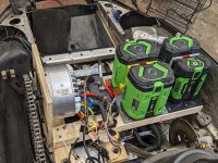
I'm converting a snowmobile to electric power: build thread. I'm using EGO Power+ 10Ah and 12Ah packs in parallel. I'm planning to disassemble the 12Ah pack at some point to find out what cells are in it.

I've designed a 3D-printable mount for the packs that they latch into. I'll publish the CAD and STL for it in the future. For now I'm putting two packs directly in parallel (in the picture below the rightmost two packs are just in storage, not electrically connected).

I'm pulling about 80 A max from the two packs, which seems OK, but they do sag quite a bit. Based on my observations, I'd say 40-50 A is about the maximum to safely pull for a long time period from a 10Ah or 12Ah pack.

One interesting discovery: the BMS doesn't seem to notice when you draw power from the packs, so the state of charge indicator (5 LEDs) on the end of the pack doesn't update. In other words, if you fully charge a pack, then discharge it through the +/- connections, then press the button on the end, all 5 LEDs will light up showing the pack at 100% even though it's not. I guess the power tool talk to the BMS and inform it of power drawn in some way. As soon as I plug a discharged pack into the charger, the appropriate number of LEDs light up, so it seems the charger gets the BMS to update its state of charge estimate in some way.
 

Attachments

  • engine bay.jpg
    engine bay.jpg
    904.2 KB · Views: 22
Reviewing an hour long video from Utube channel "Thrifty Tool Shed", the link will be provided at the end of this posting. He actually takes the EGO BMS board and repairs it. It is a far more complex board than I expected, lots of components on this board. So we're not just looking for a simple BMS chip. He figures out some interesting things in his troubleshooting process. Some things he says don't seem to be completely accurate, so regard each comment carefully.

I do see the primary current conductors going to the main connector PC Board, but I also see a number of small conductors going to that board. So I cannot rule out that there is some additional circuitry on that board, as the number of small conductors was more than four, so that would indicate something more on that board than just the four connector pins. More questions. Perhaps they are redundant wires. Perhaps they have temperature sensing on this battery connector.

There is a clock/calendar chip on the board PCF85163T, this is perhaps how they do the 30 day timing without consuming much power.

There are two somewhat proprietary microcontrollers. A DC converter to power the circuits from the battery.

The battery LED flashing green every 2 seconds and the battery end getting warm indicates that the processor induced 30 day discharge cycle is going on, according to the troubleshooting chart in the manual.

A transistor, MJD117 was shorted on his BMS, he replaced it and this seemed to fix it, however his cells had been drawn very low so they may also have suffered some damage.

video:
I really like this forum. I posted the EGO repair video years ago (first one I opened up) and we were simply learning as we go with these. We have learned a lot about them. Thanks for sharing what we learn together on these! You guys are awesome!
 
A TI BMS is a good guess, especially since they use a 1-wire protocol. However, I don't think it's what's being used in this case,
shows a few 8-bit microcontrollers, but no QFN parts which most of the TI parts seem to be (Edit: apparently there are a few TSSOP parts). It's a bit difficult to figure this out since the battery BMS is potted.

I've ordered a spare charger and a "for parts" battery to disassemble and am planning to sniff the bus during charging sometime in the next few weeks to try and identify or reverse engineer the protocol.


Has reverse engineering been carried out
 
I have a Rambo ebike that I rescued from being scrapped but it did not have a battery. I've been using the battery from a Jetson ebike but would like to use an ego 5ah battery. The controller on the bike has the 4 terminals like the ego battery but it only utilizes the +/- terminals. Would the ego battery work if I only used the +/- terminals on the battery?
 
I have a Rambo ebike that I rescued from being scrapped but it did not have a battery. I've been using the battery from a Jetson ebike but would like to use an ego 5ah battery. The controller on the bike has the 4 terminals like the ego battery but it only utilizes the +/- terminals. Would the ego battery work if I only used the +/- terminals on the battery?
Can work because he doesn't have a battery protection board. If possible, it is recommended to uses greenworks,
 
At 6:36 this guy uses solar panels to charge his 14S batteries. There are a LOT of 48V nominal charge controllers and solar panels that put out the required 55V+ in order to charge 13S packs, but I don't have definite answers for 14S


I just checked the EGO website, and they are now carrying a solar panel and charge controller for 56V EGO packs.

Click here ---> EGO Solar Kit
Wow!... mowing lawns sure has changed. I wore out half-a-dozen mowers over 4 seasons for 5-20 bucks a cut. Judging from that boy's Ego lawn care stash, he'd need to charge... what... 100 to 500 bucks each lawn just to break even. Add in his $50k Tesla, and I suspect he'll be knee-deep in debit for v-e-r-y long time.
 
There are a LOT of 48V nominal charge controllers and solar panels that put out the required 55V+ in order to charge 13S packs, but I don't have definite answers for 14S
I use a Victron 150-35 controller - I've seen absorb reach 57.6V. (4.11V/cell @ 14s). Not tried, but may go even higher.
 
What a great thread. Here I am trying to go the other direction — using a 52V nominal 21Ah battery I already have to (hopefully?) power an Ego mower I just got. It kicks on for a moment with just +/- but dies soon after with what the manual describes as a data connection timeout. Makes sense. A prior thread over on Arduino [1] wasn't able to figure out what the D connection is/does, but I'm curious how one might spoof it. There are several third-party batteries available for the Ego system at this point, and they do work! So someone cracked the concept. 🤔 Anybody have any insights on that D line?

[1]: How to interpret these binary pulses (from EGO battery pack)
 
How about just recording the data response from a battery to the device, and playing it back when the device asks for it?
 
What a great thread. Here I am trying to go the other direction — using a 52V nominal 21Ah battery I already have to (hopefully?) power an Ego mower I just got. It kicks on for a moment with just +/- but dies soon after with what the manual describes as a data connection timeout. Makes sense. A prior thread over on Arduino [1] wasn't able to figure out what the D connection is/does, but I'm curious how one might spoof it. There are several third-party batteries available for the Ego system at this point, and they do work! So someone cracked the concept. 🤔 Anybody have any insights on that D line?

[1]: How to interpret these binary pulses (from EGO battery pack)
Hello, there is no need to try to decipher any codes. All you need is one pack. you can make your own strings of 14 cells and connect to up to the battery terminals. Just make your own connector to the tool and run wires to your own pack. i have 6p 14s in a small box and it works fine. use the same charger, just put a terminal on the front with a connector.
 
Hello, there is no need to try to decipher any codes. All you need is one pack. you can make your own strings of 14 cells and connect to up to the battery terminals. Just make your own connector to the tool and run wires to your own pack. i have 6p 14s in a small box and it works fine. use the same charger, just put a terminal on the front with a connector.
I'm not sure I'm totally following — do you have a picture you could post to help me see?

It sounds like you're suggesting getting ahold of a donor EGO pack then essentially connecting its master + and - to the BMS of the donor pack (?) then also to the tool, while connecting the D line to the donor BMS... essentially putting the donor BMS in the middle and letting it 'believe' the custom 14s battery is actually its own?
 
Only just came across this thread despite owning and using Ego stuff for over 6 years!
I always planned to do similar and power them with my own built batteries, but after grabbing a bargain on a used hedge trimmer years ago that also included a 5AH battery, that combined with my pre-existing 5AH battery has always been enough to run my mower, chainsaw, etc. So to date I've had no need to do anything else.

Realistically, if one of the batteries did die, I would just replace all the cells with something better and keep the original form factor.

Cheers
 
Yeah, while I'm still marginally interested in the idea of running my mower on my 52V/21Ah pack, I've come to find that the EGO batteries themselves seem to be very high quality, have a 3 year warranty from EGO, are UL listed, and charge up in a hurry (with their upper tier chargers). While they're more expensive, I'd likely go the route of using EGO batteries on the bike rather than vice versa (if I didn't already own the 52x21). Super happy with them.

Not sure if others have noted this either but it does appear that EGO caps their battery chargers below 58.8, somewhere around 57.6-57.7? I wonder if they did this for built-in longevity with the cells. Between that and the auto-discharge-to-30%, even well used EGO batteries seem to perform really well!
 
Back
Top