unknown BMS

Gregb

100 W
Joined
Apr 28, 2010
Messages
187
Location
Canberra Australia
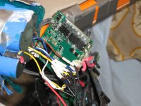
I have just bought a used LiFepo4 battery from a friend and have opened it to find it appears to have some sort of BMS built in. It is a 26V 10AH.
I am trying to identify the BMS to see what it does. It looks far superior to the one that came with my original battery (same supplier) which was the dreaded AE-LMD17 which did not work due to abysmal construction.
This is about 6cm square and has a processor on board. Everything has been painted with something that hides all the markings. I have tried removing it to no avail. There are what could be 4 transistors or FETs It is double sided and of course has a lot of surface mount tiny components.
It has LT-PAO7 V1
2008.08.28
RoHS
printed on it. Has anyone come across this as I would like to know its capabilities, especially if it has a discharge function. It definitely has balance wires connected to it. It looks like I will have to wire in another plug as it's is a size smaller than my BVM-8s. PS the supplier is long gone and he wouldn't discuss the batteries when he was still in business. I don't think he had a clue anyway and just bought them from any chinese supplier he could. He kept telling me he was an ex navy electrical engineer but that is open to discussion......in my opinion.

the cells themselves are blue , 13 cm long and about the same diam as a d cell and have some printing I can't read
Thanks
Greg

PS the solderer is of the school that believes the more you put on a joint the better..... :shock: :shock: :evil:

PPS. It also has a 3 pin socket on it which may provide unused alarm/control points??
 
Cells sound like headways.
With perhaps 1 fet for charging and 3 for output, we can expect a reasonable rating. Perhaps 25 amps.

But come on Greg'o. Where's the pics?
 
that red wire that is cut on the BMS and to the left there in the picture, was it always cut or did you do that?

that may be the O2 micro OZ790 and it is the same as the smart BMS from BMS battery. it was the processor used on the old ebike-kit.com alloy cased lifepo4 packs for the BMS.
 
No I cut it to separate it from the battery so I could wire a parallel set of sense wires for my cell log. (that is what the white sleeves are) The plug is too small. It seems to work altho on charge it has let some cells go to 3.75V according to the cell log.
So I think I will disconnect it and just use my iCharger and the new sense wires and the alarm function on my BVM8s on the bike to warn me of low volts.
 
i thought you had to cut it to peel the BMS out in space so you could look at it. but big red wires with full pack voltage should not be in the BMS.

you shoulda unsoldered the red wire from the BMS itself, it should not be there. a lot of these BMSs use the red wire to carry the signal for the top cell back onto the BMS to save the cost of one sense wire and extra pin on the plug. gives you an idea of how tight the profit margin is on this stuff.

anyway that wire is huge and it is less than about 1mm away from the B_ lead from the battery so the risk of shorting it right there on the BMS is extreme. big wires and dead short across the battery can lead to unreal consequences. this is how fires start.

i recommend people remove the big wire and use a small wire to the BMS, for the sense wire connection, and then connect the big red wire directly to the controller and bypass the BMS.

what is the problem you are having with this BMS? does it not balance the pack or is it shut off at the mosfets?
 
It is allowing 2 cells to be charged to 3.8V for a start. Haven't left it on long enuf to see what happens to rest of them. Also don't know if it has LV alarm or cutoff function. Don't know if there is a software update available as I don't know what brand it is.
 
that is totally normal. it is hard to make the lifepo4 balance closely after it has been used for awhile. the BMS will allow the voltage on the cells to climb up to 3.9-3.95V before turning off the charger mosfet.

it will keep doing that until all the other cells catch up in charge and the voltages are split evenly among all the cells in series and then the voltages merge to one small range of voltages controlled by the balancing voltage of the BMS.

so your BMS is acting normal but to get the pack balanced you will need to leave it charging and you may wanna force it to balance faster by using a big power resistor or light bulb to drain charge off the high cells while it is charging to cause the high voltages to drop as the low cells continue charging up and climb in voltage.

in short, nothing wrong.
 
dnmun said:
.

i recommend people remove the big wire and use a small wire to the BMS, for the sense wire connection, and then connect the big red wire directly to the controller and bypass the BMS.

what is the problem you are having with this BMS? does it not balance the pack or is it shut off at the mosfets?
Thanks for the advice but it is not possible to remove it, See above about solder. I am afraid I could overheat the board. It is wired from a common point of the charge and discharge wires and is used to power the BMS and itself is the common point for the charge wires. Why so thick? I have no idea probably easier to use same piece of wire. There is NO chance of a short as it is smothered in hotmelt. and it helps hold the board firmly in place with all the gaffa tape they have used.... :shock:
I don't think it is particularly good that they go so high, my iCharger never goes over 3.61. I have never seen a manufacturer site that encourages that.
Do you know if it has LV cutoff function?
 
i would expect it has the LVC functioning.

i guess you don't understand about the balancing. it is normal for some cells to be high and some low when you initially are charging and balancing a new pack or one that has been sitting for a long time, as is this one.

after the pack has charged up and the pack voltage is close to the charger voltage then the charging current is reduced to a trickle called the balancing current that continues to charge up the low cells and drains the voltage off the high cells as it balances. then the voltages end up congregated around a voltage that is the charger voltage divided by the number of cells.

the older the pack the harder to make them balance close in voltage.

but there is nothing wrong with that BMS.

yes, the BMS uses the red wire for circuit current, but it is a tiny current and you can use a tiny wire. they all just use the B+ lead on these things.
 
Please don't assume I know nothing about balancing. I also know that my iCharger stops at 3.6v and that most BMS should do as that is what is recommended in the professional literature. And while the wire doesn't need to be that thick it does a mechanical job of holding the board in place and to try and unsolder it would result in unnecessary heat to the board and possible damage. It is also well insulated so there is nothing at all to be gained by changing it.
The zephyr people (Gary et al) went to a lot of trouble to get that right and if I hadn't got one of the bad early boards (my fault for not checking it out first) I wouldn't have this problem... :| If I get some spare time and cash I may get one of Zenid's latest versions it is much later than mine and a lot fewer components.

All I wanted to know was if anyone could identify it so I could look for any literature on it.
thanks anyway
 
Back
Top