Upload Your Circuit Schematics & Requests Here...

xyster

10 MW
Joined
Jan 2, 2007
Messages
3,089
Location
Visualize Rural Sheep
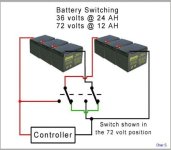
I saved a schematic from the old V by Chas S. for a series/parallel switch.
Perhaps we can construct a schematic-dedicated thread, and if the powers that be agree, they can stick-ify it to make circuit searching and reference easy.
Requests for schematics can also be posted here.

Fech-master has some good ones; the controller bypass and regen-relatad circuits are historically popular requests.
 

Attachments

  • series_parallel_schematic.jpg
    series_parallel_schematic.jpg
    21.4 KB · Views: 70,684
It's been stick-ified.

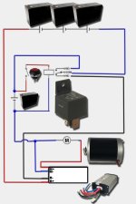
Here's a schematic of how to run a 24v controller on 36v. The Vego controller is shown, but the same techinque works for many others, like the Voloci (36v to 48v mod).
 
Basic 36v controller bypass with 12v "turbo" boost.

(Schematic edited for readability.)
 

Attachments

  • bypass_circuit.jpg
    bypass_circuit.jpg
    49.5 KB · Views: 70,573
Xyster i see a voltage boost, but everything is still going through the controller, i dont see any bypass.
Joe
 
Xyster i see a voltage boost, but everything is still going through the controller, i dont see any bypass.

I'll improve the schematic so the routes are easier to follow. B- is routed by the relay around the controller, directly to the battery.
 
Keep in mind that with most controllers the B+ and M+ wires are connected straight through. The "controlling" happens on the negative leg.
Another nice feature is if the power for the relay coil comes from across the motor wires so you can't accidently go turbo when you're stopped.
 
fechter said:
Another nice feature is if the power for the relay coil comes from across the motor wires so you can't accidently go turbo when you're stopped.
This must be bench tested and adjusted with a series resistor.
mech701 didn't, and when parking he touched the throttle and it ran into a wall, 1 welded relay, 2nd relay stopped it.
he had a 24v coil that triggers at 13v on 48v.
see http://community.webtv.net/MATTGRU/turbo
 
Another nice feature is if the power for the relay coil comes from across the motor wires so you can't accidently go turbo when you're stopped.

True, but you'd also lose the benefit of being able to use the bypass to get home if the controller died.

What's the simplest way to retard the sudden jolt when the relay's engaged with the vehicle stopped?
 
xyster said:
True, but you'd also lose the benefit of being able to use the bypass to get home if the controller died.

I haven't. I carry a jumper wire to turn on the relay. then i would hit the 500amp master switch to get home. it is large enough not to weld, and i can twist the key forcefully if it sticks.
 
The old Zappy had a SCR in series with the coil that needed some back EMF from the motor to enable. You had to physically push the scooter up to a few mph before there was enough voltage to allow the relay to engage. This prevents relay activation when stopped.

I can't think of a way to "dampen" the startup jolt without having some resistance in series with the load. This would sort of defeat the turbo action.
 
OK, back to schematics:

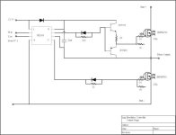
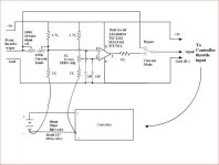
Here are some partial schematics for sections of the Crystallyte black box controller. I reverse engineered these, so there could be differences or mistakes.

For a discussion on the Crystallyte controller, see:
http://endless-sphere.com/forums/viewtopic.php?t=158&postdays=0&postorder=asc&start=0
 

Attachments

  • Brushless Controller Current Limiter.jpg
    Brushless Controller Current Limiter.jpg
    23.9 KB · Views: 70,537
  • Brushless Controller Output stage.jpg
    Brushless Controller Output stage.jpg
    17.9 KB · Views: 70,490
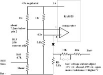
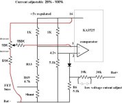
Now, if you want to have an adjustable current limit, this mod should make the limit adjustable from about 25% to 100% of the limit determined by the shunt.
 

Attachments

  • brushless_controller_adj_current_mod3.jpg
    brushless_controller_adj_current_mod3.jpg
    25.9 KB · Views: 70,476
Here's the schematic for the "current mode" throttle adapter.

For a discussion on this circuit, please go here:
http://endless-sphere.com/forums/viewtopic.php?t=78
 

Attachments

  • Current Mode Controller 2.jpg
    Current Mode Controller 2.jpg
    25.9 KB · Views: 70,458
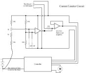
This is an adjustable current limit add-on circuit. This should work with any controller that uses a hall throttle. It will not work with most Curtis controllers.
 

Attachments

  • Current Limiter.jpg
    Current Limiter.jpg
    23.3 KB · Views: 70,411
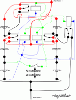
I came up with this while pondering a NiMH pack before settling on lithium. It's assumed the relays have 24 volt coils. I'm pretty sure this works :) But please check it to make sure!
 

Attachments

  • 72_volt-48_volt_switching_circuit.gif
    72_volt-48_volt_switching_circuit.gif
    38.9 KB · Views: 53,314
Ouch! my brain hurts trying to follow that.
I see the idea, it does look like it would work, but...
when designing a battery switching setup, it's important to configure it so that any possible combinations of relay states won't result in a short circuit to the batteries. When relays switch, sometimes one is a bit faster than another one, so they might not be in the proper state all the time when switching. Relays can stick or fail to operate also.

I'll see if I can figure out a fail safe version of this. Sometimes it's not really possible without adding extra switching, which is also nice to avoid.
A combination of states that shorts the controller, but not the batteries should also be avoided since the capacitors discharging might weld the contacts.
 
Ouch! my brain hurts trying to follow that.
Compared to like your current-control throttle, I'd think this circuit would be a piece of cake for you!

Would using FETs in lieu of relays avoid these problems?
Would FET switches be more synchronous?
Are FET switches less likely to fail to switch?
 
xyster said:
Ouch! my brain hurts trying to follow that.
Compared to like your current-control throttle, I'd think this circuit would be a piece of cake for you!

Would using FETs in lieu of relays avoid these problems?
Would FET switches be more synchronous?
Are FET switches less likely to fail to switch?

It makes my brain hurt too, LOL, we are spoiled by circuit design software where everything looks perfect :wink:

This may be a silly question, but when you say 24 volt coils, you aren't taking about coils that max at 24 volts? Otherwise, some of those will have in series are way over 24 volts.
 
It makes my brain hurt too, LOL, we are spoiled by circuit design software where everything looks perfect

I should get myself some of that software. Know of any good programs for the mac?

This may be a silly question, but when you say 24 volt coils, you aren't taking about coils that max at 24 volts? Otherwise, some of those will have in series are way over 24 volts.

I meant SPDT relays that switch at ~24 volts like these:

http://www.allelectronics.com/cgi-bin/item/RLY-472/500700/24_VDC,_SPDT_80_AMP_RELAY_.html
 
36 to 72 is lots easier.
i'd use one 4PDT toggle switch $3.85.
it has center OFF for emergency use. that's it. one switch.

but that looks pretty xy :shock:
 
36 to 72 is lots easier.

Yes, but that'd been done already. A schematic is on page one of this thread. Where's the challenge anyway? :)

From my experience with the scooter, I knew I wanted to run FT with at least 48 volts, but the crystalyte controllers won't handle the double, 96 volts (with the batteries fully charged to over 100V that is). So with NiMH cells in subpacks of 10 or 20, that left 48/72 or 48/84 as the only options. I even bought four 80amp relays for this!

But strangely, I didn't even think of using a 4PDT switch like you just did. That'd work with this circuit, wouldn't it?
 
xy
if i wanted 48v and 72v i'd use 7 sla. and 2 switches. it is a good combo. Mine would leave the 7th sla without a buddy pair, however.
If your circuit works with relays, a 4pdt would eliminate the failure problem fechter mentioned. I wire 2P in parallel to double the amp capacity.
 
OK. Second attempt at 72 Volt 20 AH To 48 Volt 30 AH Switching Circuit, this time with Matt's 4PDT switch instead of relays. Sorry about the excedrin headaches, guys, I don't yet have any schematic software :)

Seems like it should also work with a 4PDT relay. But the only ones I can find so far have contacts rated for 25 amps or less, like these:

http://www.digikey.com/scripts/DkSearch/dksus.dll?Detail?Ref=307352&Row=773338&Site=US

http://www.nteinc.com/relay_web/pdf/RLY16_17.pdf
 
a good 4pdt switch is CAT# STS-71 allelectronics.com rated 15a, but 2p is 30a, and they underrate it.
 
Back
Top