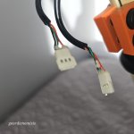
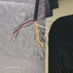
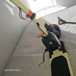
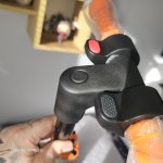
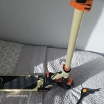
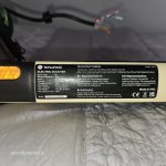
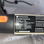
You have two hall sensor throttles, one performing the throttle function and the other the variable braking function. My guess is that the black red green on the controller side (missing the housing) is the throttle. There are no wire color standards, but this is often the case. They will mate with the corresponding throttle connector and wire color order. The brake wiring will need more testing, but my approach would be to get the throttle working first.
Before doing anything, read this guide’s section on throttle testing. You will need a multimeter to test, even a cheap one will do.
***** 8-16-2018 Welcome to the Hall Sensor Throttle Thread! If there is something you'd like to add, correct, needs better explanation, or have a question about... feel free to Private Message me. Better yet, open a new thread in the "Trouble Shooting...
electricbike.com
Once you verify the throttle wiring on the controller side (likely red 5v, black ground, ang green signal, you can connect to either of the “throttle” connectors to test which lever is which, then make that connection and you are half done. For testing, you may be able to temporarily insert the pins into the corresponding connector, and the placing them in the housing after testing.
With the “easy” connection done, repeat the controller side verification of the yellow, orange, and white wires. They will mate with the corresponding red black and green on the brake connector.
The most important thing to avoid is shorting the 5v and ground wires on the controller side, so be very careful. Read the guide and ask questions here if you are in doubt.


![pro-acjOdaaN[524].jpeg pro-acjOdaaN[524].jpeg](/sphere/proxy.php?image=https%3A%2F%2Fendless-sphere.com%2Fsphere%2Fdata%2Fattachments%2F207%2F207779-acfdd02091143439c9dc3eff56163096.jpg&hash=d820f3b08fa392ccb89e9c0dcdb9d49a)
