Windings: basic questions.

Status
Not open for further replies.
Punx0r said:
Oh, and care to draw a circuit diagram or two showing voltages and current for your diode idea in its on/off states? It's a little hard to picture and I have a feeling quantifying the variables might provide some clarity.

I don't think there's any need for a diagram; it's simply described.

Imagine taking a motor, split each coil through one of the end turns and join the turns back together by inserting a diode such that the supplied voltage flows uninhibited and the back-EMF is prevented from flowing from one turn to the next; and thus one coil to the next.

You've got the same motor -- barring perhaps a little extra DC resistance.

What happens when you connect the supply and turn up the dial?
 
Diodes wouldn't allow the current to flow because current is constantly switching directions as the motor rotates. And the back-emf is sinusoidal in a PMSM, so it would screw that up too.
 
Browser said:
I don't think there's any need for a diagram; it's simply described.

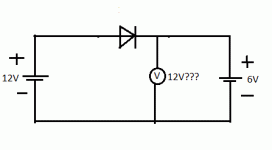
Well, based on your description, I think it boils down the to simplified diagram below. Regardless of whether you let the EMF from the winding "out", it's still there on the other side of the diode opposing your applied EMF. Practical issues of polarity and non-idea diodes aside.

Untitled.gif
 
Punx0r said:
Browser said:
I don't think there's any need for a diagram; it's simply described.

Well, based on your description, I think it boils down the to simplified diagram below. Regardless of whether you let the EMF from the winding "out", it's still there on the other side of the diode opposing your applied EMF. Practical issues of polarity and non-idea diodes aside.


Agreed. But what actually happens when you switch it on?
 
I think you've got 6V P.D. across the right-hand side no matter how many fistfuls of diodes you throw at it. Maybe it's an over-simplification and not representative of a snap-shot of what goes on in a spinning motor fed by PWMed DC, but that's how I see it based on your sparse description...
 
Punx0r said:
I think you've got 6V P.D. across the right-hand side no matter how many fistfuls of diodes you throw at it. Maybe it's an over-simplification and not representative of a snap-shot of what goes on in a spinning motor fed by PWMed DC, but that's how I see it based on your sparse description...

It was just a thought experiment and has already served its purpose; but none the less, here's my take on it. Remember, the description starts with a normal, working motor, to which we add the zeners.

At any given point in the commutation cycle, two phases are excited. And we concentrate on one pair of adjacent windings of the two excited phases acting on a single magnet located somewhere between the two. In the normal motor, one will be pushing (repelling) that magnet, and the other will be pulling.

However, In our modified motor, one of the two phases will not be getting any EMF due to the presence of the zeners. For the sake of the experiment let's assume that its the pushing phase not getting any EMF.

So what happens. The puller still pulls; so the magnet still moves. As the magnet moves, its field will impinge upon both coils, and will still induce back-EMF in both of them. As you rightly pointed out earlier, in the puller phase, although the zeners prevent the back-EMF from flowing between coils, it is still there opposing the EMF that can flow into each turn of the coil; and the net effect is essentially the same as if the zeners were not in circuit.

Where it gets interesting is in the pushing phase. The absence of any EMF in the turns of that coil mean that the induced back-EMF has full reign to accumulate and flow throughout the coil. And, as when any current flows in a conductor, it will create a magnetic field around it. And the fields around the individual turns will accumulate and reinforce within the centre of the coil -- be that a stator tooth or an air core.

But as we know, the polarity of the back-EMF in that pusher coil will be reversed from that of the EMF that would flow were it not for the zeners. Likewise, the magnetic field it induces will be of opposite polarity to that which would have been produced by the EMF. In other words, that coil will become a puller instead of a pusher with respect to the PM that is located between the two coils.

So, for each magnet, we have one coil to one side pulling, due to the field caused by the EMF. On the other side we have a second coil, also pulling in the opposite direction, this time due to the field caused by the back-EMF.

A tug of war where the EMF is working for us -- working to rotate the motor in our desired direction; and the back-EMF is working against us, trying to rotate it the other way.

Now, I asked what happened at switch on. When the EMF begins to flow, the motor is stationary, so there is no back-EMF; but equally, there is no EMF in one of the two phases, so we've effectively halved the torque of our motor. But, it still turns, and in the right direction.

As it turns, the blocked phase starts to produce back-EMF, that is attempting to turn the motor in the opposite direction. Of course, at low RPM, the magnets are moving slowly and so the back-EMF is minimal; but still it is clear to see that the back-EMF is always working against our goal of rotating the motor in our desired direction.

And when the commutation direction reverse; all the forces involved are reversed; and the same thing occurs. That EMF that flows is working for us; and any back-EMF is working against us.

Bottom line: Just as you cannot have LIFT without DRAG; IT DOES NOT MEAN that (and I paraphrase) "DRAG is fundamental to how a wing produces LIFT". Hoards of aero-designers have spent the last 100+ years minimising DRAG in order to optimise the production of LIFT. Whether that's aimed at lifting more weight in a transport aircraft (analogy:traction motor); or to create the same lift from less thrust (and fuel) in a passenger jet (analogy:Sun Racer); or to allow a fighter plane to fly faster (analogy:Formula-E).

So, whilst you cannot have an electric motor without back-EMF; IT DOES NOT mean that "back-emf is fundamental to how a motor produces power".

Bland, meaningless aphorisms of this nature, and all that they imply, are why whilst the web has given us hugely greater access to a huge range of expertise; it has also given access to an even greater pool of 'armchair experts'; who's primary expertise is selling themselves as that which they are not. Discipulum cavete.
 
As I've already said, I meant "converts", not "produces" and anybody who reads my entire post where I said that and the following post that I wrote can see I was talking about power conversion not production. As far as my expertise, I haven't tried to sell myself at all (although I certainly could...) because my argument speaks for itself.
 
He hasn't even thought it through. If you have diodes on the three legs then in a Wye connection you will get zero current and in a delta connection you might possibly get current to flow through 2 legs but there won't be any commutation it will just lock into place and you'll have a nice heater.
 
Perhaps 10 years ago I spent a day thinking about a way do reduce BEMF and not lose torque/amp until I realized it would violate the law of conservation of mass and energy.

Existing motor tech has achieved ~99% input to output mechanical efficiency, to improve it beyond that 1% remaining ultimately requires having an additional energy input source. If you find a way to tap some additional abundant energy source, then you will care even less about the efficiency of your motor which won't be exceeding 1:1 input to power output using copper and iron and magnets.
 
Two thing I would like to clarify in this thread:

1) Is it accurate to say that eddy currents are induced in the winding in a spinning motor due to a gradient in field strength, but that this loss is so small that there is no advantage in using a foil or litz wire winding to try to reduce it?

https://en.wikipedia.org/wiki/Electromagnetic_induction#Parasitic_induction_within_inductors
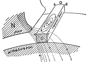
300px-Hawkins_Electrical_Guide_-_Figure_291_-_Formation_of_eddy_currents_in_a_solid_bar_inductor.jpg
In this illustration, a solid copper bar inductor on a rotating armature is just passing under the tip of the pole piece N of the field magnet. Note the uneven distribution of the lines of force across the bar inductor. The magnetic field is more concentrated and thus stronger on the left edge of the copper bar (a,b) while the field is weaker on the right edge (c,d). Since the two edges of the bar move with the same velocity, this difference in field strength across the bar creates whorls or current eddies within the copper bar.


2) There is a considerable opinion on this forum that vehicles should use low bus voltages should be used in combination with high Kv motors, giving many practical and safety advantages, while maximising system power density, with no efficiency penalty. This is persuasive, yet out in industry, all the high tech motors appear to use high voltages to (seemingly) maximise efficiency and power density. How can this be reconciled?
 
Punx0r said:
Two thing I would like to clarify in this thread:

1) Is it accurate to say that eddy currents are induced in the winding in a spinning motor due to a gradient in field strength, but that this loss is so small that there is no advantage in using a foil or litz wire winding to try to reduce it?

All of the latest research says no.


Punx0r said:
2) There is a considerable opinion on this forum that vehicles should use low bus voltages should be used in combination with high Kv motors, giving many practical and safety advantages, while maximising system power density, with no efficiency penalty. This is persuasive, yet out in industry, all the high tech motors appear to use high voltages to (seemingly) maximise efficiency and power density. How can this be reconciled?

I have two answers for you on this one.

a) Different types of motor have different goals. You should not expect the same methodology applicable to axial flux traction motors to be the same as aero-model motors were maximum torque is not an overriding requirement. A truck need torque, but not so much in the way high revving bhp. A sports car on the other hand blend of both. And a land speed record car needs as much bhp as it can muster.

b) There is a lot of opinion on this forum that is of the self-reinforcing type. One man expresses an opinion, or justifies his choices, and others concur and follow suite. Pretty soon, received wisdom becomes immutable law of the universe.

I started out as a MechEng., destined to become a draughtsman. My first 'for production' piece of work was a towing eye for a Bedford TK military truck. It was one of the endless variants that were produced and something new had been fitted such that the existing towing eye was now blocked.

So, I was given a spec to work to; a minimum eye diameter of 1 1/4", and capable of being used to tow (from memory) 14 tons with displacement angles upto 40 degrees and a factor of safety of 100%.

So, I set about finding a new position to mount it; and performed the calculations to determine the thickness of materials required etc.

I drew up my design: basically a lump of flat bar with a hole through one end and the outside radiused to give an even thickness of material around the hole in the pulling direction;and showed it to my boss. "Work up a view showing that in situ at the new position." Which I did.

"Hm. You're sure of your calculations?"

"Yes." (He checked them anyway.)

"Make the bar 50% thicker and wider enough that you can put 50% more material around the hole."

"Did I make a mistake in the calculations?"

"No. But it'll look better if you beef it up a bit. YOu know what the military are like."

The difference between builders and designers: Builders build something and hope it works. Designers design something and hope that the builders won't make to many "improvements".

Thanks for at least giving me rational discussion Punx0r. A breath of fresh air.
 
liveforphysics said:
Existing motor tech has achieved ~99% input to output mechanical efficiency,

At what speed (rpm)?

As the rpm increases, the increase in commutation frequency mean that the copper losses increase rapidly and efficiency falls of equally so.

If your application requirements allow the use of low speeds, like direct drive e-bike motors, it is not an issue.

But if your application calls for higher speeds, then reducing those AC losses are paramount to efficiency.

It is those AC losses I am seeking to limit. (And, at least in simulation, achieving).
 
learningrc said:
He hasn't even thought it through. If you have diodes on the three legs then in a Wye connection you will get zero current and in a delta connection you might possibly get current to flow through 2 legs but there won't be any commutation it will just lock into place and you'll have a nice heater.

A) it was a thought experiment. But, I guess thinking isn't a strong suit here abouts!

B) It is obviously beyond your imagination that there are other ways of connecting 3-phase coils beyond wye and delta. Eg. You could take all 6 leads out and connect them to the mosfets.

(Hint: using 4 leads is a mass production economy measure, but by no means a necessity.
 
Lebowski said:
Just my € 0.02 : a motor with reduced backemf (as meant by the OP) comes down to a perpetuum mobile and is therefore impossible.

Have you ever been disappointed by someone you held in high esteem?

My assessment of your assessment of my heavily researched, careful explanation: Lazy, reactionary and polemic.

I expected more; but that's probably my own fault.
 
learningrc said:
As I've already said, I meant "converts", not "produces" and anybody who reads my entire post where I said that and the following post that I wrote can see I was talking about power conversion not production.

Have it your way; whilst you cannot have an electric motor without back-EMF; IT DOES NOT mean that "back-emf is fundamental to how a motor converts power".


learningrc said:
As far as my expertise, I haven't tried to sell myself at all (although I certainly could...) because my argument speaks for itself.

If the cap fits; defend, defend, defend.
 
Punx0r said:
2) There is a considerable opinion on this forum that vehicles should use low bus voltages should be used in combination with high Kv motors, giving many practical and safety advantages, while maximising system power density, with no efficiency penalty. This is persuasive, yet out in industry, all the high tech motors appear to use high voltages to (seemingly) maximise efficiency and power density. How can this be reconciled?

A final thought for you since there's nothing left for me here:

Do you know why national grids are run on very high voltage AC?

(Long story short; but look the history of how it came about; it makes for fascinating reading.)

It all comes down to I*I*R. For any given length of conductor (resistance), the power consumed as heat rises with the square of the current flow.

So, if you raise the voltage, you can lower the current to transfer the same quantity of energy. Less current == lower losses. Hence grid transmission lines carry hundreds of kilovolts.
 
Browser said:
So, if you raise the voltage, you can lower the current to transfer the same quantity of energy. Less current == lower losses. Hence grid transmission lines carry hundreds of kilovolts.
Pity that doesn't apply to electric motors.....
 
down here in the little island at the arse-end of the earth where i am, they still use national grid 12v200,000A dc power, copper transmission lines the diameter of a stormwater drain :lol:....yeah, thats bs too..

im enjoying this thread, between the straightout gunslinging, there are some really interesting counter points of veiw,
a good dynamic nebuli of ideas in which to learn stuff..
 
Miles said:
Pity that doesn't apply to electric motors.....

Hah. It's a fundamental law of physics; but you think it "doesn't apply".

And you take pride in your 'knowledge'.

Sums things up nicely I'd say.
 
Lebowski said:
Many grids are switching over to DC...

"Many" is an overstatement, and it doesn't change my point. They still use high voltage/low current to avoid I*I*R losses.
 
Status
Not open for further replies.
Back
Top