Wiring CA v3 to generic controller

Joined
Feb 19, 2022
Messages
19
1000002975.png
Hey gang,

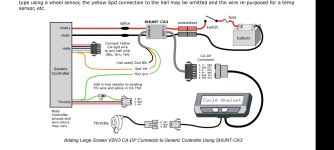
Trying to wire according to this setup to my Ariel Rider D-Class controllers (display died so decided this was the time to upgrade). Have a new CA v3 that has an adapter from the W8 to DPS, connected to the Grin shunt. Pulling the ThO over to what appears to be the ThO on the Ariel Rider throttle input (they have weird names in what little documentation they have). I don't get anything happening at the motor. CA sees the throttle and I see voltage move up and down on ThO in the way I'd expect. Any idea what I'm missing here? There's not really any documentation on the Ariel Rider controllers (asked support and they said they're custom and didn't have anything to share besides basic pin outs).

Getting a bit frustrated after getting all the grin gear and worried the answer may be (you need new controllers too...). So would love any tips/tricks/thoughts.

Best,
Josh
 

Trying to wire according to this setup to my Ariel Rider D-Class controllers (display died so decided this was the time to upgrade). Have a new CA v3 that has an adapter from the W8 to DPS, connected to the Grin shunt. Pulling the ThO over to what appears to be the ThO on the Ariel Rider throttle input (they have weird names in what little documentation they have). I don't get anything happening at the motor. CA sees the throttle and I see voltage move up and down on ThO in the way I'd expect.

There's going to be a few things to check. First, it's not clear why the display died, and so whether the display was the only issue, or if you may have had a controller problem causing the display issue (common). It's also not totally clear whether you have replaced the controller or not. If so, a link to the new one would help. If not (which is what it sounds like), then:

If the controller you have had a display on it, then that display is probably required for it to operate, or at least to work beyond basic defaults. If you have to press any buttons on the display to make the bike operate, the display has to be there and working to do this.

If the display was used to turn the controller on, then it almost certainly does so by connecting battery voltage from the controller to display back to the controller again, in the display/controller connector. You can do this manually, but you'll probably have to figure out the wiring by opening up the display (since it's broken, you can't make it worse, right? ;) ). We can help with that, but we'll need pics of the board inside the display, where the cable solders to it.


If the controller is not the original and does not have a display, and is not intended to work with one, then it should operate with either direct throttle control, or that from the CA.

If on the CA Diag screen (one left of main) you can see Throttle out voltage in the correct voltage range for your controller, then if the controller isn't doing so, it's either not fully wired up with everything it needs to turn on / enable it, or it's not correctly wired to some part of the system, or it has a problem.

You can find out if it's turned on by checking the voltage on any of the 5v wires of the controller, without the CA connected to it. If there's no 5v, either the controller is not turned on, or it's got another problem.

We can go from there once there's more info to go on.
 
Wow, really appreciate the quick and thorough response.

The controller is original (technically there are two, since the D-Class is dual motor, but the second is slaved to the first using a three way switch to toggle power between them). There's not documentation on what voltage the controller expects on the ThO, so am just using defaults right now (assuming 5v). Given that default, I'm seeing throttle out like I'd expect on the display (and verified at the wires with a multimeter).

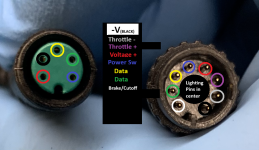
Here's the best I could get from Ariel on what comes out of the display and routes into the controller. The left pins are what came out of the old display. The right is the bundles 8-pin that goes into the controller. That grey wire appears to be the ThO best I can tell by tracing back to the throttle itself.

I'll pop open the display tomorrow and post an image of the board here. Thanks for the help!

1000002976.png
 
There's not documentation on what voltage the controller expects on the ThO, so am just using defaults right now (assuming 5v). Given that default, I'm seeing throttle out like I'd expect on the display (and verified at the wires with a multimeter).
You can tune the throttle voltage later, but for now you can set it up so that the CA just outputs the identical votlage range that you see from the throttle itself. (since presumably that throttle worked on the original system correctly).


Regarding throttle - and throttle +, they won't do anything without a signal voltage, or if one of those is a signal voltage, a ground, or a 5v; throttle needs all three to work. So before you connect the CA's wires to anything, get the controller powered up and test with a meter what voltages are where, so you don't damage the CA (or controller) by wiring things wrong. ;)

If the throttle is powered by the display itself, then there's no 5v on the throttle wires in that green connector, since it only has throttle ground and signal to the controller (it wouldn't feed 5v to the controller or from it). So, knowing what voltages are on the actual connector is important for what you wire to the CA.

The CA throttle out only needs the signal wire to the controller, since it should share the ground via the battery negative. If you have to you can use a ground from the CA to the controller's throttle ground too, but this can cause problems sometimes. There should be no 5v from the CA to the controller.


Here's the best I could get from Ariel on what comes out of the display and routes into the controller. The left pins are what came out of the old display. The right is the bundles 8-pin that goes into the controller. That grey wire appears to be the ThO best I can tell by tracing back to the throttle itself.

I'll pop open the display tomorrow and post an image of the board here. Thanks for the help!
If the image is accurate, then you probably won't need to.

The Voltage + and Power SW pins are almost certainly the ones to connect together to power the controller on. If the controller doesn't get battery voltage to it's regulator from teh display, it doesn't make 5v. You can verify if it gets 5v or not when you connect it to the battery; if not, you'll need to connect the Voltage + and Power SW to power it up to make the 5v to run everything.
 
Super helpful. The throttle is not powered by the display, but they share a ground (on the cable on the right). Wiring the throttle into the CA, I can see that the grey wire (throttle - in their diagram) is the ThO (that is, the input voltages make sense, ranging from 1-4.2 v when actuating the throttle).

One weird thing: when I check the voltage out of the +/- to the display, I get voltage below battery voltage (40v on a 52v battery). When I wire the CA with the shunt, I get all the right voltages there, but the controller is outputting a reduced voltage for some reason to the display voltage wires. Also noticing that if I try those wires to power the CA, it doesn't want to come on.

On the PowerSw, can verify that the 5v was not coming through without the powersw connected. With it connected, now seeing 5v as expected.

Seeing the expected behaviour out of the CA ThO with the throttle wired into it as well. The weird is not seeing motor engage when connecting CA ThO to the controller ThO (grey wire).
 
@amberwolf any thoughts on next steps/what might be going on? At this point, I can get CA wired with the shunt but despite sending voltage to the throttle wire, I'm not seeing any response from either motor.

My default configuration before the display failed should be limiting anything and my brakes are wired to the CA not the controller.
 
I don't know the Ariel system itself in specific, but in general most of these controllers with displays will, without the display, start in some default mode. It *might* be the same default mode as with the display, or it might be a different one.

Some systems power on in mode 0, which provides no assist, no motor operation, and require the rider to press the up button on the display to change to an assist mode that allows throttle or PAS to work.

Did your system originally require you to change from the default power-on assist mode to be able to use the throttle, or did it just work when you turned the system on?

If it required you to change modes, and the controller is coming up in the same default mode without display as it did with the display, then you'll need the display to do that, or you'll have to change the controller to one that does not require a display, or find out what codes are sent by the display to the controller when you turn it on, .

If the power out of the controller to that wire is a voltage lower than the battery, and it "goes away" when a load (CA, etc) is placed on it, then it means it's controlled by a FET the same way the battery controls it's charge and discharge ports, and that FET is turned off. So there is leakage or ghost voltage on that wire. Best guess is it is for a light, and is controlled by the display's backlight/headlight control function. (so without the display, it can't be turned on).
 
Uffda. Both of those things make sense.

First, forgot that the display required a passcode to unlock. The fact that I can't enter that (because the display is dead) may be why I can't activate the motor but still have (some) power.

Your point on the ghost voltage got me thinking maybe I could try getting the display up just powering it directly from the battery but again, no dice. If the display is truly fried, then a new display might solve the problem.

That said it could also be that whatever ghost voltage was out there is part of what fried it to begin with. On the other hand, it could just be a light as you say, that is stuck open due to the display being unavailable...

But starting to seem like buying replacement display is in my future (while also tidying up the to make sure there aren't any errant shorts maybe causing the problem)...
 
What specifically happened that caused the display problem? Or, what happened just before the problem occured, and what is the specific problem with the display? (what does it do that it shouldn't, or what does it not do that it should?)
 
No idea, it just stopped working one day. It doesn't power on, despite having power to it. I checked connectivity all along the cabling and to the controller when it went out to make sure it wasn't something there.
 
If it has full battery voltage (not the ghost voltage) at the input to the display itself, all the way to it's board, then it could be the tiny transistor inside it that powers the whole system on when the power button on the display is pressed. That passes battery positive from Voltage + to both the controller's Power SW wire and sometimes other parts of the display's internals.

That usually leaves obvious physical damage when it fails, making it easier to find, but harder to know what it was to replace it....however, you can test by manually connecting the two like you have to turn the controller on, to bypass that transistor. If the display still wont' power on, then...

It could be the display's internal votlage regulator; if that's fried it won't power the MCU / etc inside the display, so nothing will work on it.


If it doesn't have full battery voltage (just the ghost voltage, or less) at the input to the display itself, all the way to it's board, then there's a fault (connector, wire, etc) between the battery and the display; you can test for this by manually connecting battery to the display directly.


If the problem is caused by the controller itself, then the display will power up with the above, at least when not connected to the controller. Whether it will power up the controller or not depends on what is wrong with the controller that caused the failure.
 
Back
Top