Scooter Dual motor controller wiring throttle wire

sonoaatta

100 µW
Joined
Aug 18, 2023
Messages
8
Location
canada
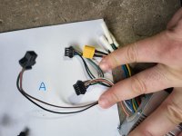
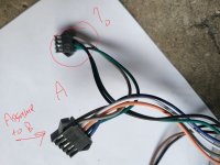
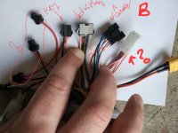
I have a dual motor scooter, the original controller died and I received two new controllers to replace. However the wiring is different, please see the image attached. Where would I be able to find the wiring or manual for this controller, there is A and B controller. The display and cable from the controller is a bit different than the 6 wire controller plug from the display, the orange wire is connected to the matching red on the display, but it can be jumped from the key power plug. So the display turns on, but there is no throttle, where does the throttle wire connect on this kind of controller?


1713077428008.png
Edit: more photos, labeled A and B for each controller, there is a white a plug on controller A, I suspect this is for throttle but I am not sure??

20240414_065713.jpg20240414_065720.jpg20240414_065723.jpg20240414_065730.jpg20240414_065735.jpg20240414_065732.jpg20240414_065739.jpg20240414_065804.jpga.jpg20240414_065732.jpg
Edit: opened the existing display with throttle the wire on the display that is not connected anything is labeled DMS on the board, what is DMS for?20240414_065730.jpg20240414_084617.jpg
 

Attachments

  • a.jpg
    a.jpg
    441 KB · Views: 2
  • 20240414_065748.jpg
    20240414_065748.jpg
    1,022.1 KB · Views: 2
  • 20240414_065720.jpg
    20240414_065720.jpg
    805.1 KB · Views: 2
Last edited:
Maybe they have a link to where they purchased them.
Otherwise you’re going to have to post better pics of each connector with each conductor clearly visible, and a multimeter to test with.
 
Maybe they have a link to where they purchased them.
Otherwise you’re going to have to post better pics of each connector with each conductor clearly visible, and a multimeter to test with.
Thank you I just uploaded more detailed photos
 
What does the cable from the motor and the cable from your existing controls/display/etc. look like. Controller A appears not to have hall sensor wires. Are these sensorless controllers?
 
What does the cable from the motor and the cable from your existing controls/display/etc. look like. Controller A appears not to have hall sensor wires. Are these sensorless controllers?
Yes they are sensorless 3 wires only, green, blue, yellow. I believe that the controllers too are sensorless. I opened the exisitng display and find the wire that is not connected to anything, it is labeled DMS on the display board. What is DMS for? (I will edit the post with a photo to)
 
Yes they are sensorless 3 wires only, green, blue, yellow. I believe that the controllers too are sensorless. I opened the exisitng display and find the wire that is not connected to anything, it is labeled DMS on the display board. What is DMS for? (I will edit the post with a photo to)
Depends on how the display and buttons works in your setup, but typically displays with 6 wire connectors would be something like Battery Positive, Ground, Transmit, Receive, Speed Signal, and Power ON/OFF. The latter is if the buttons on or connected to the display turn the controller/bike on and off. Does the display show speed? Does it or the buttons connect to it turn the bike on/off?
 
Depends on how the display and buttons works in your setup, but typically displays with 6 wire connectors would be something like Battery Positive, Ground, Transmit, Receive, Speed Signal, and Power ON/OFF. The latter is if the buttons on or connected to the display turn the controller/bike on and off. Does the display show speed? Does it or the buttons connect to it turn the bike on/off?
There is a power button on the display to turn on the display, which works as the display turns on (and it can read voltage), the odometer on the display is zero, but nothing is spinning so nothing should show on the odometer, is there a way to test it? I suspect that the controller is turned off as the black and red plug (the ones in this screenshot) measure zero voltage.

Thank you for the help

1713113130195.png

1713113161697.png
 
Does the old controller have the orange wires on the display connector? That would typically be the wire that powers on the controller.
 
AFAIK, that type of throttle/display unit doesn't output an analog throttle, it sends the throttle signal digitally via the display serial connection. They will only be compatible with specific controllers that are designed to work with those specific units; the communications between them only work for those, so the functions only work if the comms work..

There are a number of versions, such as the TF-100, LH-100, etc. Can't see enough of yours to tell which one it is. (it should have a label or be molded into the case).

A quick google on the p/n
finds this page here on ES
that shows the wiring inside the throttle unit, showing no analog throttle out.

It also finds links that provide some info for some controllers; don't know if any match yours, theres' more in the links in the search
1713118913250.png
 
AFAIK, that type of throttle/display unit doesn't output an analog throttle, it sends the throttle signal digitally via the display serial connection. They will only be compatible with specific controllers that are designed to work with those specific units; the communications between them only work for those, so the functions only work if the comms work..
The two appear to be a pair, with A possibly being the slave.
I've never quite understood how the wiring on those TF-100/LH-100 display throttles work. But, OP, with the display on, can you measure the voltages on the purple, brown, and white single JST connectors? I don't think the display harness has a 5V in for the throttle, although I see a 5V soldering point in the display circuit board pic. You could also test to see if you have a varying voltage out of one of the wires when you pull the throttle lever. Or do you know already when the display is on, which wire is the throttle signal and which is the 5V input?
 
Working on these dual-motor/2wd controllers has taught me to always buy them with the LCD display throttle included. I was in the same situation.
 
I've never quite understood how the wiring on those TF-100/LH-100 display throttles work.


The throttle is just read by the display MCU and sent to the controller as serial data, just like the mode button presses, etc.


There is no analog throttle voltage output at all, AFAICT without having one here to test; there's no wire on the one below to pass it to the controller.

From the previously linked thread, a pic of the back of the board,
1713123625079.png
where AFAIK: TX and RX are the usual, VCC is battery positive, GND is battery negative, DMS is the switched battery positive when you turn on the display's switch. (if you follow the board traces, both of those go to that transistor on the left, which is typical of the circuits used in displays for this kind of thing)

There's a number of these types of displays, but I don't recall any posted about here on ES that have actual throttle analog output...so they only work on controllers that were designed for this specific display.


I don't recall that anyone has verified that all versions of this type of display work with different controllers, but I suspect there is some firmware / etc dependence, so that not every display will work with every controller meant for these types of display/throttle unit, just like other controller/display sets. (such as kingmeter / lishui combos, where not every combo "works").
 
Thank you all for the help, i was able to figure out issue, it was stupid, but helpful for any other one who get this issue later on. So the existing display had the kickstart enabled and when I was testing the throttle I was testing with the wheel not moving. I rotated the wheel and pressed the throttle and it worked. There are still some mystery wires on the controller, but I was able to get the lights horn and dual motor switch to work.
 
Back
Top