My current Ebike build from scratch

Joe T.

100 W
Joined
Jul 2, 2013
Messages
156
Location
Ulster county New York
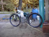
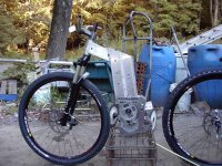
As I planned from the beginning, I will be building an Ebike from scratch. My GNG mid drive kit installed on my current bike so easily, I couldn't help but put a month or two of riding on it to feel things out.

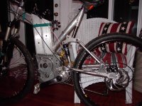
The frame, bottom bracket, motor plates, rear swing arm, and miscellaneous mounting gizmo's will be made from materials found at my local surplus store. Wheels, seats, brakes, handle bars, and the battery will be store bought items.

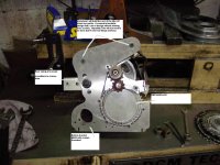
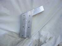
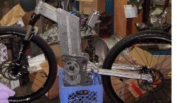
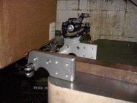
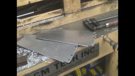
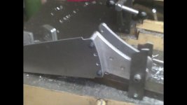
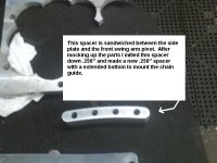
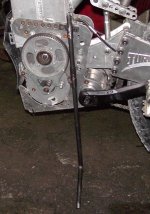
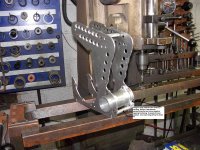
I have already drawn up plans with the basic geometry, wheel base, and motor+battery locations. Wheels, tires, brakes, fork, are here or in the mail as we speak. Also I have already built the motor plates, freewheel and bottom bracket.

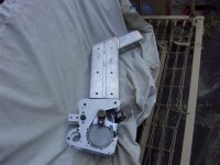
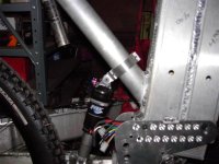
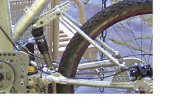
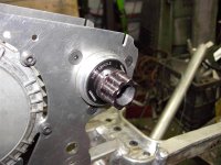
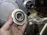
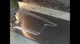
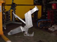
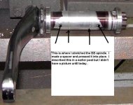
I have the swing arm front bearing portions built with bearings installed but my brain can't see the rest at this time. I am partial to a single pivot like my current MTB which was my guinea pig for this project. I have no complaints with this bike except there are a few flex issues I want to correct this time around.

I have a tig welder and CNC mill at my disposal but sadly no real metal forming tools like tube benders or breaks. This is where I'm struggling as the rear swing arm needs a few bends to line things up.

Right now I need some inspiration on the swing arm.

More to come as progress is had...
 

Attachments

  • PDR_0026.JPG
    PDR_0026.JPG
    413.5 KB · Views: 8,488
Got some frame work done this week. The battery box is intergraded into the forward tube. The bottom will be cut at an angle to create a “lean forward” position like a normal frame. A solid mount will be milled and holes drilled for attachment purposes. The welded to the box. The second picture is a basic mockup of where the pieces go. I have a cad model where I’m pulling the dimensions and angles from when cutting.
 

Attachments

  • PDR_0027.JPG
    PDR_0027.JPG
    34.2 KB · Views: 8,396
  • PDR_0028.JPG
    PDR_0028.JPG
    50.5 KB · Views: 8,396
Wow joe this looks like fun! :D

Looking forward to seeing where you take the build...

-JD
 
It's going to be a bit of a junkyard dog in the looks department for sure. 100% of the Aluminum parts are recycled. Even the motor plates were something else before I got my hands on them. I had to make small adjustments to their shape to fit the metal I had to work with. The seat and shock mounts are yet to be designed as I am waiting to assemble the steer tube and fork to see how close to my cad model the actual bike is. The swing arm is still floating in thin air as my mind can't seem to see it just yet. One of my obstacles is the wheel base. This is a trail bike that will be in the woods maneuvering around rocks and trees. The wheel base is set to be 43" center to center. This is 1" longer than my current bike but I have 29" wheels in stead of 26" so I have less space then I had on my last build. Also I rolled the motor back putting the jack shaft about 12 o'clock. This puts things out of danger but also forces me to shorten the swing arm length from before. So mechanical leverage will be different and yet again, I will need to just try something and see what the bike tells me.

After the frame is done and tested, I plan to do some weight reduction on the main body. That too may never happen but is on the list of refinements I want to do. As I test fit things I will try to get new pictures for this thread.
 
Got some progress done today. Hopefully I will have a swing arm Sunday.
 

Attachments

  • PDR_0030small.JPG
    PDR_0030small.JPG
    62.4 KB · Views: 8,310
  • PDR_0029small.JPG
    PDR_0029small.JPG
    71.3 KB · Views: 8,310
This is the swing arm. The "bolt" holding the swing arm to the frame is a piece of .500 OD .031 wall 4340 tubing. This goes through the mounting plates and has no threads to dig up the aluminum in any way. Then I made an aluminum nut with a .500 counter bore for the one end. A 1/4-20 allen bolt was pressed into a second nut that was made to fit inside the 4340 tube. A spacer with a .500 ID was added to the allen head side to allow "squeezing" the plates against the swing arm bearings when tightened. So basically the swing arm is mounted on a .500 hollow tube and a 1/4-20 allen bolt sandwiches it all together similar to a quick release wheel.

There are 4 positions the swing arm can mount. I quickly realized that it was very difficult to pull out the .500 tubing when changing mounting positions. I then spun up a small dowel with a 1/4-20 thread and a .490 OD. After removing the retaining nut you switch it with the puller nut and now you use the bolt to pull the shaft through. Also the puller nut is tapered which allows you to use it as a guide when sliding the shaft into the next hole.

This thing will be pulled apart several times during the build. I will try to take some pictures of some of the custom parts. I think the BB30 freewheel will be of interest to many ES readers.
 

Attachments

  • swing.JPG
    swing.JPG
    60.9 KB · Views: 8,227
I have a few updates to post. I have it on wheels and I'm heading to the bike shop to get a rear cassette, chain, and maybe a new seat. Here are some pictures:
 

Attachments

  • PDR_0045 (Medium).JPG
    PDR_0045 (Medium).JPG
    65 KB · Views: 8,154
Swing arm #1 was a failure. Partly from me not fully welding it before testing it out but the writing was on the wall. Other suspension issues were evident as well. The shock location was too close to the fulcrum and the leverage was well out of proportion making it too easy to push down. The only way to resolve this was to create some type of upper linkage to increase the shock travel given the space I have to work with. My resolve helped with the stiffness of the rear but was overkill on the shock speed. Now it is too stiff in the beginning and as the suspension compresses the shock becomes easier to squish. Basically it works completely backwards to what I wanted!
 

Attachments

  • PDR_0052 (Medium).JPG
    PDR_0052 (Medium).JPG
    95.7 KB · Views: 8,095
I've got it together for some test riding last night. It tips the scale @ 59#. The gearing seems to be close as I took a few trails today with no issues as far as power goes. A bit heavy up front but this is what I was expecting. This is also good for hill climbing. It seems quieter then before. The original location for the battery would have made it impossible to remove with the front fork installed. Rolling it back to clear put the battery closer to the seat then planned. In retrospect a side install battery would have avoided this change. Overall I think it's a keeper. I'll work out the shock geometry and clean up the wiring.
 
This weekend I got a chance to correct the rear shock multiplier. Before the ratio was off and basically it was a hard tail with a shock. Now there is a nice firm but adjustable rear suspension. A small reinforcement was added where the round tubing welded to the billet bearing retainer. This may need additional reinforcement but I'll wait and see. I went on a good ride just after the update and no flexing or bending was noticed.

The bottom bracket started life as an SRAM X9 that I found on ebay. My first obstacle was the spacing between the cranks. The GNG was 6.75" or there about, while the unaltered X9 was a full inch narrower. The simplest way around this was to stretch the bottom bracket spindle. Annoyingly the one crank arm was non-removable. I ended up cutting the spindle in the center with a hacksaw. Then I turned a spacer out of 6061 and pressed it into the two halves. After adjusting the crank phasing I pinned the three pieces together with tapered pins that I had left over from a job.

I went with a BB30 because I fount this nifty One way Bearing on ebay. http://www.ebay.com/itm/300876482142?ssPageName=STRK:MEWAX:IT&_trksid=p3984.m1423.l2649#ht_848wt_701
This made it simple to make a silent freewheel. A small key was drilled into the spindle which locks the inner race. The bearing is then pressed into the spider where the chain ring mounts. A small pin is pressed into the hub to lock the outer race as well. I already had some Shimano chain rings from a donor bike. These are nice because they share a single bolt pattern for both rings. This makes the spider simple to make. When finished the outer and inner spider are bolted together and this sandwiches the bearing in the center. The unit slides on the BB30 spindle and the freewheel is complete.
 

Attachments

  • new shock mount.JPG
    new shock mount.JPG
    41.1 KB · Views: 7,951
  • PDR_0047 (Medium).JPG
    PDR_0047 (Medium).JPG
    78.5 KB · Views: 7,951
  • PDR_0048 (Medium).JPG
    PDR_0048 (Medium).JPG
    82.5 KB · Views: 7,951
WOW! Awesome work, I will be interested to see what you come up with after making quite a splash with this.

The CSK-30PP freewheeling crank really deserves it's own thread (if you want). There has been quite a bit of discussion over the past few years over the possibility. The German CSK's are quite expensive, but they can definitely handle more torque and are known to last longer. The more affordable Chinese versions to not have as much torque-holding power and do not last as long, but when using a larger CSK, that might be less of an issue. I have wondered about a large CSK and a simple ball-bearing side-by-side to make a freewheeling crankset that is stable, and still extra-quiet.

The White-Industries ENO freewheel is known to very strong, but some builders are annoyed by its somewhat loud pawls clicking.
 
your design for battery holder is really a good work. It's so nice. Will like to know your performance report once it's done. :idea:
 
eva-michael said:
your design for battery holder is really a good work. It's so nice. Will like to know your performance report once it's done. :idea:

The battery itself has a channel to slide over a "rail" if you will. So I took a piece of .050" aluminum plate I had and cut it to size. Mounted it on a .093 washer with a flush mount screw. So the battery slides into the box tubing as well as locks on to the guide rail. The battery actually doesn't touch the walls on the box frame. This leaves space for me to run wires and the brake and shifter cables inside the box out of sight. That will be part of my winter "complete the bike" project.

As for performance, I'm riding the bike daily. It climbs steep hills with no wheelie problem at all. This is with a 43.5" wheel base. Actually it's hard to wheelie even if you try. A good yank on the handle bars going up a hill and you can get it to come up. Otherwise it is on two wheels.

The battery life has been great. I get two days of riding on a charge. A ride for me would be about a 14 mile loop in the woods with me pedaling 90% of the time and on motor alone very little. Hills I use pedal with power assist. I also use motor to get me up to speed on long flats and I maintain speed pedaling. This is a big help when you get tired but need to conserve battery.

I have never measured top speed as this doesn't apply to riding the mountain trails. It should be easy to calculate.

Stock GNG motor, jackshaft, and freewheel. 44 tooth driven gear and 34 on the chain back to the 9 speed casset on a 29" wheel.

All I know is it's a blast to ride. There are so many walking/bike trails where I live it's mind boggling.
 
spinningmagnets said:
WOW! Awesome work, I will be interested to see what you come up with after making quite a splash with this.

The CSK-30PP freewheeling crank really deserves it's own thread (if you want). There has been quite a bit of discussion over the past few years over the possibility. The German CSK's are quite expensive, but they can definitely handle more torque and are known to last longer. The more affordable Chinese versions to not have as much torque-holding power and do not last as long, but when using a larger CSK, that might be less of an issue. I have wondered about a large CSK and a simple ball-bearing side-by-side to make a freewheeling crankset that is stable, and still extra-quiet.

The White-Industries ENO freewheel is known to very strong, but some builders are annoyed by its somewhat loud pawls clicking.

The 30mm spindle made it easy for me to build everything to the dimmension I needed without me "Inventing" a bunch of custom parts. The bottom bracket housing was simply a piece of tubing I turned in the lathe. I modified the spindle but I used the splined ends "as is" so bearings and crank arms are off the shelf. I built the spider to accept off the shelf chain rings I had.
 
Joe T. said:
eva-michael said:
your design for battery holder is really a good work. It's so nice. Will like to know your performance report once it's done. :idea:

The battery itself has a channel to slide over a "rail" if you will. So I took a piece of .050" aluminum plate I had and cut it to ....
I have ever met a people from New Zealand who want to put 4x48V12Ah-48V15Ah(battery with aluminum case for rear rack) in the body of ebike. It's same idea as yours. This can be a way to put a a lot of battery and still keep a good look.
 
For those interested in this thread I made some winter updates to my bike. The rear swing arm evolved into a patched up and reworked mess. I got the end of the summer out of it but it was on its last legs for sure. During a ride in the power lines one of the welds failed and I had to limp it home. After the repair it never acted right. The tire would flex and rub under power. This seemed to be getting worst as time went on. It was time for a clean start.

Having made new rear dropouts for each of my attempts, I decided to make this set replaceable. Just in case things don't work (again) I can use them over. Also I have not been too happy with welded joints using aluminum. Most of my issues have been at or very near the welded areas. This time around I am adding surface area near all welded parts to spread the load.

I have a jig to hold the front and rear parts in the proper place. My plan is to work from each end and meet in the middle. I drew the parts in CAD which helped getting things to miss like the chain and sprockets.

Here are a few pictures:
 

Attachments

  • Ebike sus 3 (1) (Medium).JPG
    Ebike sus 3 (1) (Medium).JPG
    62.2 KB · Views: 7,302
My last swing arm was non-symmetrical. The right side arched over the chain and sprocket and the left side went direct to the hub. I like things that look wrong. Unfortunately some of my flex was a direct result of two different type arms. So this time around both sides will be the same. Another compromise I plan to eliminate are the secondary links connecting the shock to the rear of the swing arm. In the end I will need some type of linkage for the shock as the leverage against it is too great for the shock to handle alone. I will find room at the front of the swing arm for this.

The front is simple as it is two 3/8 thick plates of 6061 AL. I milled them to accept a tapered roller bearing race. All the pieces stack together. It can be seen in the post above. Connecting the front to the back will be some .090" plate aluminum. The sides will be double wall and welded together forming a .500" thick box.

I made a pattern in CAD and traced them out on the CNC mill. It is quite a challenge to hold a thin flat sheet down while cutting out the middle on a milling machine. I made a vacuum fixture for this job. Basically it is a flat plate with a series of channels cut into it forming a grid. A vacuum hole is in the middle and an O-ring is placed on the table to seal the work piece. You cut it leaving about .020" left to cut by hand. In some cases you can cut it with a pocket knife. I used a jig saw which cut through it like paper.
 

Attachments

  • Side plate2.jpg
    Side plate2.jpg
    23.8 KB · Views: 7,357
  • Side plate.jpg
    Side plate.jpg
    26.5 KB · Views: 7,357
  • Side plate3.jpg
    Side plate3.jpg
    18.6 KB · Views: 7,357
I added a chain guide to my old swing arm which eliminated my random chain falling off syndrome. This worked like a champ so I needed to add this to the new swing arm as well. After I installed everything on the bike I found the perfect place. A small modification to the side plate spacer and the new mount sandwiches in virtually un-noticed.
 

Attachments

  • E_bike_2014 (3) (Medium).JPG
    E_bike_2014 (3) (Medium).JPG
    69.2 KB · Views: 7,199
Before spring time gets here I plan to have the frame powder coated. Part of my problem is I don't want to scratch it up after it's done. Finally I found a place to put a kick stand. Now I don't have to lean the bike against things like I have been doing.

I took some .500" OD steel tubing that I bought and made a simple tube with a foot at the end. It slides inside two .625" OD tubes strategically placed on the frame. A snap button, like what is in a tent pole, snaps into a hole in the upper tube. There are a few choices to compensate for different levels. To put the kick stand up you push the button with your finger and swing the leg of the kick stand with your foot. This will position the snap button away from the locking holes. You then pull it up and lock the bottom into a plastic catch bolted to an unused 6mm hole in the GNG motor. It snaps in very tight, perhaps too tight. It has no chance of popping out on its own.To put it down you pull the bottom out of the catch and slide it down. Once again you push the snap button in with your finger and lock it into a suitable hole in the top mount.

It's a tight fit but nothing rubs. I took it for a quick ride and everything is out of harms way. It was very COLD out so my test ride was short..... :cry:
 

Attachments

  • Kick_stand down.JPG
    Kick_stand down.JPG
    122.9 KB · Views: 7,149
As my bike gets closer to being finished it seems to look less complete. Funny how that works.

Today I milled out my bottom bracket mounting flanges. The bike is now in pieces getting ready for powder coating.
 

Attachments

  • Ebike 2014 (2) (Medium).JPG
    Ebike 2014 (2) (Medium).JPG
    103.8 KB · Views: 6,960
  • Ebike 2014(0) (Medium).jpg
    Ebike 2014(0) (Medium).jpg
    70.1 KB · Views: 6,960
  • Stretch.JPG
    Stretch.JPG
    67.9 KB · Views: 6,957
Back
Top