
Is there a chance the bike might ever be out in the rain? Anderson PP connector facing straight up, looks like to me.On the offchance that someone else is converting a motorcycle in the same way, that also uses a fuel cap with the same shape, I managed to draw up a charge port to replace the gas cap. It uses the same holes, and incorporates a flush-mounted Anderson 50amp connector.
You are using an out of date browser. It may not display this or other websites correctly.
You should upgrade or use an alternative browser.
You should upgrade or use an alternative browser.
1989 Kawasaki EX500 (Ninja) - Second build, slow and steady
- Thread starter harrisonpatm
- Start date
If he doens't already have a "gas cap" for that (probably does) then Anderson makes various caps and plugs for their shells that wil help with this.
A-DamW
100 W
The recess on the top is for a cover that I can draw and print in TPU, to keep it watertight when it's not being charged.
harrisonpatm
10 kW
- Joined
- Aug 8, 2022
- Messages
- 824
Done and done


harrisonpatm
10 kW
- Joined
- Aug 8, 2022
- Messages
- 824
I'm just using PETG for now, supposed to have good UV resistance and I've left a DIY wind turbine with PETG parts outside for a year now with no deviation. And that's directly in the weather 100% of the time. This small cap that will live most of its life under cover should last ok.Gotta love 3D printing. Especially on diy projects. I’ll be printing all my own XT60 surface mount charge ports too! TPU for the covers and CF-Nylon or ASA for the mounts themselves. Thanks for sharing!
I have small kids in the house so I don't print nylon or other materials that can leech semi-toxic gasses. I'd like to, or at least mod my setup to vent outside.
harrisonpatm
10 kW
- Joined
- Aug 8, 2022
- Messages
- 824
Boring update, got the seat recovered. The foam underneath was fine, no molding or crumbling. That was nice, because I didn't want to have to either 1., find an original seat in better condition (pricy), or 2., purchase a generic seat and modify the frame to fit it. A family member of mine had a stash of vinyl seat covering for a boat upholstery project, and while light grey wouldn't have been my first choice, I couldn't pass up the free fabric. I think it looks pretty good, I don't mind the seat being lighter in color than the rest of the build. Besides, budget is going to be the deciding factor on the whole build, and I like the challenge of using the colors/materials/products that are available and finishing around those constraints.
I left the foam seat out in the sun for a couple of days to make sure it was "sanitized" and ready for a new cover.

I haven't recovered a seat before, there's still plenty of wrinkles, but it looks alright and I have enough material leftover to rip it off and do it again if I decide I hate it. Besides, I won't have to look at it if I'm going to be sitting on it!


I left the foam seat out in the sun for a couple of days to make sure it was "sanitized" and ready for a new cover.
I haven't recovered a seat before, there's still plenty of wrinkles, but it looks alright and I have enough material leftover to rip it off and do it again if I decide I hate it. Besides, I won't have to look at it if I'm going to be sitting on it!
The foam underneath was fine, no molding or crumbling. That was nice, because I didn't want to have to either 1., find an original seat in better condition (pricy), or 2., purchase a generic seat and modify the frame to fit it.
If you ever need to do it, you can re-foam a seat using kits from places like Smooth-On, etc., depending on the specific foam you want to use.
Or you can cut apart an old sofa / recliner seat cushion that is a big foam block, into the right shape.
harrisonpatm
10 kW
- Joined
- Aug 8, 2022
- Messages
- 824
I'm going to build and complete the wiring for all the 12V accessories ahead of time (lights, horn, signals, ect). I can build and test it with a 12v source, and later on power it from the 12v converter off the main battery in the final design. Treating the 12v wiring harness separately from the powertrain wiring is what I did on my last build, and I can do it without having to decide on the main expensive build components in my spare time. Plus it's cheap; all of the 12v accessories are already here, on order, or leftover from other projects.
I feel like upping my organization from last year's hand-drawn scratch diagrams. What's an easy free electrical schematic program that I can use to draw this? Google suggested tinyCAD. Is there a better/easier one that I can get started on? I don't regularly make schematics, so I don't want to spend a ton of time learning a new program, if that's okay. Any suggestions?
I feel like upping my organization from last year's hand-drawn scratch diagrams. What's an easy free electrical schematic program that I can use to draw this? Google suggested tinyCAD. Is there a better/easier one that I can get started on? I don't regularly make schematics, so I don't want to spend a ton of time learning a new program, if that's okay. Any suggestions?
Since you probably don't really need to draw an actual circuit schematic like iwth individual diodes, transistors, chips, etc., you probably don't need something designed to do that specifically. (doesn't hurt if you want that functionality, but....)
I usually just use the paint program in Windows and just make blocks for various parts, and draw wires to them as lines, matching the color of the wires actually used wherever possible. Disadvantage is it's all one layer and is bitmapped, not vector, so youc an't just move things around easily.
Offfice suites (open source or paid) should have a vector program (like openoffice draw) that would make it really easy with minimal learning curve.
harrisonpatm
10 kW
- Joined
- Aug 8, 2022
- Messages
- 824
Thank you! I usually sketch it in pencil first anyway, it'd just be nice to have a neat, color coded and labeled diagram, and I'll probably want vectoring so I can move things around when I make changes, so I'll check on openoffice drawSince you probably don't really need to draw an actual circuit schematic like iwth individual diodes, transistors, chips, etc., you probably don't need something designed to do that specifically. (doesn't hurt if you want that functionality, but....)
I usually just use the paint program in Windows and just make blocks for various parts, and draw wires to them as lines, matching the color of the wires actually used wherever possible. Disadvantage is it's all one layer and is bitmapped, not vector, so youc an't just move things around easily.
Offfice suites (open source or paid) should have a vector program (like openoffice draw) that would make it really easy with minimal learning curve.
A-DamW
100 W
I have usedI feel like upping my organization from last year's hand-drawn scratch diagrams. What's an easy free electrical schematic program that I can use to draw this? Google suggested tinyCAD. Is there a better/easier one that I can get started on? I don't regularly make schematics, so I don't want to spend a ton of time learning a new program, if that's okay. Any suggestions?
draw.io
quite a bit, you can use it online or download and run local.
Github page for download:
Releases · jgraph/drawio-desktop
Also, I like their mission statement:
About draw.io
Last edited:
harrisonpatm
10 kW
- Joined
- Aug 8, 2022
- Messages
- 824
I went to the site, played with it for 5 minutes, now I'm in love. Appreciate the recommendation!I have used
draw.io
quite a bit, you can use it online or download and run local.
Github page for download:
Releases · jgraph/drawio-desktop
Also, I like their mission statement:
About draw.io
harrisonpatm
10 kW
- Joined
- Aug 8, 2022
- Messages
- 824
Alright, thanks @A-DamW , great drawing program recommendation. Throwing my 12V wiring harness up for comments and critique:

I decided I'd like my ignition switch to control all 12v accessories, but I was thinking the key switch I purchased may not be able to handle the amperage of the entire 12v system, plus the contactor coil. Then I smacked myself in the forehead, because I realized cars manufacturers must do this with a relay. Sure enough, $6 40-amp 12v automotive relay from Amazon to save the day. Duh, that was an easy fix.
As for the rest of the wiring, it was such a fun program , I went ahead and drew up a hypothetical powertrain wiring diagram as well:

I'm going to cross-post this diagram in my other thread regarding contactor-controlled BMS's, because this is the route that interests me the most so far, and it's open to discussion there as well, as there is more than one way to go about that route.
Looking forward to comments. I'll go ahead and wire the 12V accessories for fun in the next couple of weeks and report back how that went.
I decided I'd like my ignition switch to control all 12v accessories, but I was thinking the key switch I purchased may not be able to handle the amperage of the entire 12v system, plus the contactor coil. Then I smacked myself in the forehead, because I realized cars manufacturers must do this with a relay. Sure enough, $6 40-amp 12v automotive relay from Amazon to save the day. Duh, that was an easy fix.
As for the rest of the wiring, it was such a fun program , I went ahead and drew up a hypothetical powertrain wiring diagram as well:
I'm going to cross-post this diagram in my other thread regarding contactor-controlled BMS's, because this is the route that interests me the most so far, and it's open to discussion there as well, as there is more than one way to go about that route.
Looking forward to comments. I'll go ahead and wire the 12V accessories for fun in the next couple of weeks and report back how that went.
harrisonpatm
10 kW
- Joined
- Aug 8, 2022
- Messages
- 824
On one of my junkyard runs, I was able to score several lengths of high-voltage cables from EVs, so it'll be great material to use for battery cabling and whatnot.

When I had originally gotten this a few months ago, I didn't look hard at it before, just threw it in the corner. Now I took a closer look to organize my basement, and got interesting surprises. I found that the fabric-like sheath they used on the cables was completely and easily removable, so now I have several lengths of bright orange wire sheath for my 12v harness and whatever other wiring. That'll be a plus in the "aesthetics" box.

On the other hand, when I cut off the EV connectors to take a look at the cable, I was a little bit disappointed. The cable insulation was 3/4" thick, so I was expecting something like 00 gauge. Unfortunately:

Is anyone else familiar with this cable, and why EV's need shielding for the main + and - cables? Didn't think that was necessary, educate me.

Still, it's not too disappointing, because the gauge of just the inner conductor ended up being equivalent to #2 gauge cable, or good for 125amps. If I end up wanting more amperage, I can always double up and parallel conductors, because of the price savings by getting it from the scrap yard: I got 40 feet of it for 20 bucks, or 50 cents a foot, compared to the same product on being $3-5 per foot online. And the aesthetics! Gotta keep everything orange now.
harrisonpatm
10 kW
- Joined
- Aug 8, 2022
- Messages
- 824
I was able to find this cable after some digging:
 www.omgevcable.com
So this particular cable I got says it's good for 165 amps, excellent. Still a great find.
www.omgevcable.com
So this particular cable I got says it's good for 165 amps, excellent. Still a great find.
ev high voltage cable-ev battery cable-ev motor cable-OMG EV Cable
OMG provides orange EV HV Cable. The ev high-voltage cable are used to connect the charging port and the battery, the interior of the battery, the battery and the motor, and the battery energy storage…
harrisonpatm
10 kW
- Joined
- Aug 8, 2022
- Messages
- 824
Haven't added too much to the project recently, since it's a low priority project, and I've been working on elements for my home solar system as well. But I have had it in the back of my mind a lot, and I've been looking harder at this thread and some other sources at people's mid-drive builds. Even though I would personally prefer a hub motor, there are some rather nice builds out there that showcase the benefits that a mid drive would give.
Having said that, I wanted to ask opinions: Does anybody think that the QS130 would work for this build? On paper, I think it won't, but I wanted to see what others think. My reasons for it not working is because on my current, 365-pound build, it takes 5kw continuous to ride at 50mph constant, on a flat surface (peaks of like 8-10kw for acceleration, ect). I know that the ninja should be 50-100 pounds lighter than my current ride, but I would also like the top cruising speed to be a bit higher than 50mph this time. Therefore, I could expect this build to see something like 6-7kw constant power draw if I want to cruise at 55-60mph, and perhaps 70mph for a few minutes. I know that QS underrates their motors, there are so many examples on this forum of people who regularly run their motors higher than their on-paper rating. But still, qs138 is rated for 3kw continuous on paper, so I don't think I can realistically expect it to run at twice that every day, I'd be asking for trouble.
And if the QS 138 wouldn't work, would the QS165 work, with it's 4kw continuous rating?
And if the QS165 wouldn't work, then I don't think I'll go for the QS180, because at it's price point, I'd rather stick with my original choice of a hub motor.
Eastwood
100 kW
- Joined
- Jan 13, 2021
- Messages
- 1,479
The QS138 can handle 7kW of continuous power. I think the real question is, how long do you plan on running that continuous power for highway speeds? If we’re talking 20 minutes or less that could work.
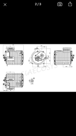
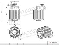
The better option is the QS 138 V3 90h. It’s rated at 4 kW compared to the 70H at 3 kW. Posted pictures below so you can see the spec differences.
You could consider upgrading the phase wires. It would lower the resistance and also act as large heat sinks. Leaving the phase wires exposed to airflow at speed will also help with cooling. Then the bigger the phase wires the more the airflow is going to help with cooling.
What hub motor/s are you considering, QS 273?
138 v3 70h

138 v3 90

The better option is the QS 138 V3 90h. It’s rated at 4 kW compared to the 70H at 3 kW. Posted pictures below so you can see the spec differences.
You could consider upgrading the phase wires. It would lower the resistance and also act as large heat sinks. Leaving the phase wires exposed to airflow at speed will also help with cooling. Then the bigger the phase wires the more the airflow is going to help with cooling.
What hub motor/s are you considering, QS 273?
138 v3 70h
138 v3 90
Attachments
Last edited:
harrisonpatm
10 kW
- Joined
- Aug 8, 2022
- Messages
- 824
Thanks for the more specific knowledge. I was eyeing the 138 because its price point is stellar compared to what I've been considering so far, and even though it takes up room where the battery would go, I would probably use Li-Ion on this build and could afford the battery space. And it seems doable because I've looked around and I feel that with its size and weight, and my limited fabrication capabilities, I could likely work out how to mount it myself. I really really like the mechanical simplicity of hub motors, but the 138 has a lot of bang for its buck.The QS138 can handle 7kW of continuous power. I think the real question is, how long do you plan on running that continuous power for highway speeds? If we’re talking 20 minutes or less that could work.
The better option is the QS 138 V3 90h. It’s rated at 4 kW compared to the 70H at 3 kW. Posted pictures below so you can see the spec differences.
You could consider upgrading the phase wires. It would lower the resistance and also act as large heat sinks. Leaving the phase wires exposed to airflow at speed will also help with cooling. Then the bigger the phase wires the more the airflow is going to help with cooling.
What hub motor/s are you considering, QS 273?
138 v3 70h
View attachment 340511
138 v3 90
View attachment 340512
Realistically, I personally believe that highways themselves aren't terribly safe for motorcycles, and I haven't used them in the past year in my area. So I'd be talking about, at most, jumping on the highway for 2-3 miles for a shortcut, if I'm feeling brave. Or, pushing 75mph in a 65mph zone for 30 seconds to get past slow traffic. So yeah, 20 minutes or less.The QS138 can handle 7kW of continuous power. I think the real question is, how long do you plan on running that continuous power for highway speeds? If we’re talking 20 minutes or less that could work.
I have seen this on both your build thread and others, and if I got a mid drive, any mid drive, I would definitely do that.You could consider upgrading the phase wires. It would lower the resistance and also act as large heat sinks. Leaving the phase wires exposed to airflow at speed will also help with cooling. Then the bigger the phase wires the more the airflow is going to help with cooling.
My two hub motor options which I am considering, are either scrapping my current ride and stealing its 273 8000w 16-inch rim, which I believe would be more than adequate. For that, it's a big ask, because there's nothing wrong with my current ride and I would need some financial incentive to do that to it. Or, purchasing the 273 17-inch rim @ an upgraded 12000w, if I was going to purchase something new. But that's gonna be like $1000-1500, so unlikely. Option 3 would be to get lucky on the "for sale" section of this forum or my local classifieds, for either hub motor or mid drive. Budget really is gonna be the deciding factor.What hub motor/s are you considering, QS 273?
peadar
100 W
Any chance you could tell me the distance eye to eye on the ex 500 bog bones,Still liking my plan of taking the restoration/conversion slowly, and in the meantime I've begun to cleanup and restore the gross old frame. Which is actually one of my favorite parts, I love scraping all the mud and muck off the old machinery, repainting, and putting it back together.
View attachment 335446
View attachment 335447View attachment 335448View attachment 335449
That rear shock is pretty good shape, but does anyone know how to disassemble the whole assembly? I'd really love to take that spring off and really get in the cracks. Couldn't find a specific method on YouTube so far, any hints?
Also thinking about color scheme. On one of my junkyard runs, I was able to score several lengths of high-voltage cables from EVs, so it'll be great material to use for battery cabling and whatnot. As well as the cables coming out of the big QSmotors are also orange. So why not orange as the color scheme for the whole bike?
How's this shade?
View attachment 335450
I was thinking that it's probably unlikely that I will be able to find a full set of plastics that fit, so I want to consider naked bike options. Which I like anyway, because it'll be obviously an electric motorcycle with an exposed battery. So I was thinking about painting the frame orange, instead of black, since it'll be visable.
Here's a sample pic I found online of someone else's (IC) naked mod of the same model bike, in which the frame is painted a bright color to contrast the rest of the bike, and I thought it's something that I could manage.
View attachment 335451
harrisonpatm
10 kW
- Joined
- Aug 8, 2022
- Messages
- 824
I don't know what "bog bones" are, can you be more descriptive? I'm not a motorcycle guy by nature, so if that's a common slang for something, I don't know what it is.Any chance you could tell me the distance eye to eye on the ex 500 bog bones,
peadar
100 W
it for shock link , one on each side of the shock, working on ride hieght with R6 shock on a 250I don't know what "bog bones" are, can you be more descriptive? I'm not a motorcycle guy by nature, so if that's a common slang for something, I don't know what it is.
they might be about 135mm / 165mm? link arm with two holes is see misprint dog bones
sorry about that
harrisonpatm
10 kW
- Joined
- Aug 8, 2022
- Messages
- 824
Ah, dog bones. Good one, that's exactly what they look like.
Sorry for the low quality pics, I have bad light in my basement. Looks like 160mm OC.


You suggested that 165mm is an option, and you could be right, but it looks to me like 160mm dead on. Hopefully that helps.
Sorry for the low quality pics, I have bad light in my basement. Looks like 160mm OC.
You suggested that 165mm is an option, and you could be right, but it looks to me like 160mm dead on. Hopefully that helps.
peadar
100 W
thanks for picsAh, dog bones. Good one, that's exactly what they look like.
Sorry for the low quality pics, I have bad light in my basement. Looks like 160mm OC.
View attachment 342101View attachment 342102View attachment 342103
You suggested that 165mm is an option, and you could be right, but it looks to me like 160mm dead on. Hopefully that helps.
140mm is what i need plan b will be to cutdown the stock ones ahd have them welded,have cut them down and it seems to be made of good stuff
I can highly recommend a bunch of these to fix that. Just install the tiny screw-in clips to the cieling, walls, etc., even under tables/shelves for easy seeing in those areas, snap the tubes in place, then plugin the wiring to series them (up to X number of them at a time depending on the specific model/brand). There are now higher wattage options (brighter) than the 22W ones I got. On mine you can link 7 in series, so one outlet runs 7 lights for quite a lot of lighting.I have bad light in my basement.
I have that many in the bedroom in a rectangular arrangement on the cieling for direct lighting, that competes with indirect daylight outside for brightness and color. Another pair behind a wolf-picture-wall hanging for indirect lighting (can pull the hanging aside for more direct lighting when needed). (because I do a lot of small projects while laying in bed, so I can at least get something done when i'm too wiped out to sit at a desk or whatever and need to doze periodically to keep going).
There are probably much better ones, but I've been using all 20 of mine for a few years now in the kitchen, bedroom, backroom workspace, and under the awnings outside, and only two of them have had any issues--each of those has lost one LED out of the dozens inside.
I even use a couple of them as portable light bars on extension cords, so they get banged around a LOT, and they still work. :lol:
(I did kill the PSU in one by trying to use a dimmer on it...so don't do that.
") ..but the LED strip still works if I connect the PSU from a different one to it).
..but the LED strip still works if I connect the PSU from a different one to it).

These have been alright too; one in the bedroom with a DIY adapter to fit the cieling fan light socket :lol: and one in the washer/dryer/utility room. Been using them for years, too, but I only consider them a good deal because the ones I got were "repackaged" and something like half price at the time. The light is bright but doesn't all go where I want it to. They probably work much better in larger spaces or outside to light large areas than small rooms.

There are other useful options too, but those are both pretty easy. Some of the ones I've tried out are here
LED Lighting projects
EDIT: thread has mutated a bit into LED COB projects, as these are much cheaper than trying to work out a ballast solution for CFLs, starts a few posts down. So...Lowe's has a good deal on these 65w "4500 lumen" 6500k (bright blue-white) CFLs, at less than $3 each...
Similar threads
- Replies
- 43
- Views
- 2,106
- Replies
- 3
- Views
- 349
- Replies
- 20
- Views
- 1,014