TMaster said:
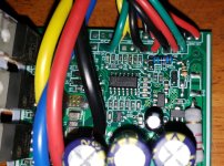
The 2 regluators in the picture are a 78L05 5V and the one next to the end of the big resistor is a 78L15, 15V.
Interesting. Most of the stuff I've seen uses the LM317 instead of the 7815 to create the 15 (or 12) v output, that then feeds to the 7805, to create the 5v output.
I wonder if they are also running their inputs in parallel from the resistor, rather than the above series usage?
I also wonder if they are running the LM339 (the quad comparator that makes up the controller "brain") off the regulators, or off the resistor input? (could be done either way, as it usually handles the same range as the 78xx series)
Either way, the resistor is still being used the same way--drop the input voltage down just enough to keep it within the limits of the regulators--it just depends on the load being relatively constant and sufficient to cause enough current to create enough voltage drop.
For 48v, that's a max charge typically of 52v for lithium (13s "liion"), but lots of brushed controllers are used iwth lead systems, which is four 12v (13.6v-14.4v "full" or "charging") bricks, so 4x 14.4v worst case usually, or 57.6v. Max charge of another common "48v" battery in these, LiFePO4, would be 16s x 3.65v = 58.4v.
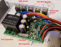
Calculating 0.035A x 1180 ohms (1.18k) Im getting a voltage drop of about 41V. That seems like a lot, considering Normal nominal voltage of a 48V pack would drop it to only 7V for the regulator input. Now, I'm not totally sure what the current or amp draw is on the circuit, I'm just guessing on the .035, from previous experience. Both the 05 and 15 regulators can handle 35V max.
The current itself doesn't really "matter" for your purposes.
If you need the current for something (such as power dissipation required by the resistor) you can calculate it as volts / ohms. Just measure the actual voltage across the resistor, which you already know the resistance value of (it's marked by the stripes as 1.2kohm 5% tolerance per https://www.calculator.net/resistor-calculator.html). .
If the voltage drop on the existing resistor means it's output is well below the max for the devices it feeds, then you can probably use the existing one as-is. If it's marginal, you could change it for a higher value.
If you need to calculate a new resistor value, then if I did it right then the "divide the new voltage (58v) by the old one, and multiply the existing resistor by the result to get the new higher value." would (assuming 13s lithium, or 54v full previously) be 58v / 54v = 1.074 x 1200ohms = 1288ohms.

")