Adding hall sensors to outrunners

Gwhy?

What was your best unloaded current (input to controller) at what measured voltage for the larger 80mm motor? I just got external sensors fitted using your template for the large Turnigy HXT (C80100-130) and saw 5.9 amps at 53 volts WOT with a 12 FET Keywin controller. That is about 300 watts and the motor windings got up to 120 F. How touchy was your adjustment? I guess when we first set up the brackets it is random as to where the sensors are relative to the windings. Adjustment should find the current minimum somewhere along the adjustment range.

Thanks for your pioneering work here!

Dave
 
dbaker said:
Gwhy?

What was your best unloaded current (input to controller) at what measured voltage for the larger 80mm motor? I just got external sensors fitted using your template for the large Turnigy HXT (C80100-130) and saw 5.9 amps at 53 volts WOT with a 12 FET Keywin controller. That is about 300 watts and the motor windings got up to 120 F. How touchy was your adjustment? I guess when we first set up the brackets it is random as to where the sensors are relative to the windings. Adjustment should find the current minimum somewhere along the adjustment range.

Thanks for your pioneering work here!

Dave

Hi Dave the lowest WOT no-load current for my large motor was around 5.5A @48v this was after I removed the skirt bearing ( which sucked an additional 1A !) I would say your not far off with your setting as it is . Yes you adjust the sensors position until you get the lowest current, The best way I found to do this is adjust the position of the sensors while you are running the motor and keep a eye on the current meter, but just have the motor ticking over not WOT. I spent quite a bit of time trying to find out if this was "normal no-load current" for these big motors because this was my main concern about how hot it would get but it would appear to be normal from what other people have said and from the tests I carried out I couldn't find anything wrong with my motor except the skirt bearing was shot from new. If its the newer type of motor that you have i.e with the skirt bearing what I found helped to get a better thermal path to the out side world was to put some thermal grease between the matting surfaces between the the parts on re-assemble ( I wish I took some pics of this because its hard for me to describe ).
 
ive got some halls mounted up inside the big turnigy "130 kv" motor, and its now running well.
no luck as yet with them outside -allways noisy or maby interference from the coils magnetic field, hopefully the photos come up to show it.

i changed the motor to Y from delta so it matches to voltage and currents the most controllers and packs are running, and i expected lower idle (circulating) currents for the same rpm -it worked out about the same though. but the motor should now be about 75kv.

so after much pissing about, i got it to run smooth on halls with a 12fet infinion, took ages to tune the exact individual hall positions for precise matching of each phase emf by running the motor with a drill -ie 0 deg timing, the hall traces are dead clean at all rpms and all exactly 120 deg apart, it ran smooth at 75kv (2900rpm 1.79A 39v), and can tick over at super low speed useing only 1.5w!
BUT this was not the best setting, with the timing advanced lots, the rpm went up to 3500 (using 2.9a) so this is nearly 90kv, or 155kv! (in original delta).

at this advance the motor had noticeably less torque at low rpm and the extra current draw is not cool. then i ran it on 79.6volts and this advanced setting (at 6500rpm) was acctually the lowest current draw, (a bit up and down?) but not that good at crawling speed. and now (6000+rpm) at 0 deg timing the sound is harsh and the draw higher.

so we now have a very narrow window for optimum timing to cover all rpm ranges, but the zip folder has this final setting on the cro compared to 0 deg setting. set for the best compromise -careing mainly for a low idle current, now the motor spins at 6300rpm at 79.6v and 2.51a so its 79kv (or 137kv delta) at about 200w used idleing its as low as i can get it and toward the max rpm for this motor without wads of extra heat and losses.

the formulas now show peak efficiency of 94% at 82a, 6527w in 6136w out with 200w (idle) + 200w (ir) -about 10Nm at 6000rpm.
so much torque and smooth crawling ability, now bolting to bike..
 

Attachments

  • P1290646.JPG
    149.2 KB · Views: 2,050
  • New Compressed (zipped) Folder.zip
    39.9 KB · Views: 255
Excellent work mate haven't been game to try myself as yet waiting for spare motor so i can have a play without messing with the running bike.

Would you be open to accepting $$$ for converting Outrunners with halls maybe? If so what would you charge?
I couldn't be so lucky that your in Australia could i haha...well done anywayz mate.

KiM
 
Nice work toolman,

I like the way you can adjust the timing with this internal arrangement 8) .

On your 'scope pictures, where did you connect the probes to measure the back EMF, accross 1 isolated phase or between two phases with the motor connected in wye?

It is tricky to see in the picture, but it looks like you are using the 17.1 degree mechanical spacing between the sensors, and that it is fitted to the version of the motor without the skirt bearing?

Is it an easy task to separate the winding terminations and convert the motor from delta to wye?

Sorry for so many questions, -but this is good stuff!!

Burtie
 
KiM
Dont be afraid of fitting hall sensors to your motor. If you dont mind just glueing them in the stator slots, which works well on my Stinky, it would be a very easy job for you to do (considering some of the amazing stuff I have seen you produce in the past :shock: 8) )

You usually need to take these Turigy motors apart to fix the bearings anyway!

Go for it.
Burtie
 
AussieJester said:
Excellent work mate haven't been game to try myself as yet waiting for spare motor so i can have a play without messing with the running bike.

Would you be open to accepting $$$ for converting Outrunners with halls maybe? If so what would you charge?
I couldn't be so lucky that your in Australia could i haha...well done anywayz mate.

KiM

yep , i am in oz (canberra unfortunately) and could help you get halls sorted, so maby if you post up a photo of yourself wearing i nice big frock, then ill see what i can do..
-jeez you do meet some weirdos on the internets. :shock:


all fair questions burtie,
the scope setup: you hook ch1 signal to a hall colour (say blue) and earth to the common hall blacks. ch2 sig to the blue phase wire and its earth to the green phase wire.

i usually use the controller (still hooked up) to power and load the halls in the normal way, but DONT hook up the controller phases to anything or it all gets i bit smoky (ask me how i know) as the scopes earth's are linked.
it sounds tricky but its not, the phases are now just floating.

you then do the same for say the green hall (ch1) and ch2 sig to the green phase and earth to the yellow phase
and then.........................the yellow hall (ch1) and ch2 sig to the yellow phase and earth to the blue phase.

-might sound odd but it becomes simple cos then all you are looking for is a dead match (in direction and position) between each hall and its (same colour) phase, this would be 0 degrees timing, the motor will then run the same forward or reverse with any normal controller, and most hub motors seem close enough to this standard.

the need for more advance than this (all shown in the zip file a few posts back) is prolly cos of such high rpm, and is maby correcting for lag in the controller or something??

my halls ended up 10.205 mm apart centre to centre and they are 1 or 2mm inboard of the magnets diameter -how many degrees? , and yep its an early non skirt bearing motor.

it was a bit of pain to separate the windings but they didnt need to be cut, but it seems worthwhile cos now it is usable with higher voltage battery packs and normal 12 fet controllers now have a better chance (1.73 times better) of getting torque out of the motor.
when i ran it in delta it was just to hard on the controller and i was stuck haveing to run over 12 4110 fets and under a 50v pack -in summary the controller get hot and the motor didnt!
 
Excellent work, Toolman2! So we now have a benchmark for setting up the large HXT's. It looks like you used some perfboard to mount your Halls? In your opinion do we need to do the winding separation to use the HXT's with the 12 fet controllers?

Dave
 
Im am going to make myself some hall sensors as spares for my 64mm and 80mm motors the same as I have made before, as I am making the pcb's I was wondering if anyone would also want one ( as its not to much trouble to make additional ones ) I only have enough hall sensors for my 2 spares but I would order some more halls if enough people want a complete sensor for there motors ( potted and tested with fly leads), the pcb's will be shaped and drilled ready to be assembled if you would like just the board. If anyone is interested please PM me with your requirements. pcbs will be £3.00 uk pounds
+PP, a fully assembed, potted and tested sensor will be £25.00 uk pounds +pp.

Pic of hall sensor as a reminder:


halls potted.jpg
 
gwhy! said:
Im am going to make myself some hall sensors as spares for my 64mm and 80mm motors the... If anyone is interested please PM me with your requirements. pcbs will be £3.00 uk pounds
+PP, a fully assembed, potted and tested sensor will be £25.00 uk pounds +pp.

So the 80mm would work for the 80-100 130kV HXT motor? Yes, I noticed the 80, I just want to make sure you're referring to the left number and not the right one.
 
dbaker said:
Excellent work, Toolman2! So we now have a benchmark for setting up the large HXT's. It looks like you used some perfboard to mount your Halls? In your opinion do we need to do the winding separation to use the HXT's with the 12 fet controllers?

Dave

yep it just the grid pattern board with single row traces.

i have the bike running now with 11.25: 1 gearing and 60v (loaded) pack, and a std 4310? 12 fet ecrazyman controller set at 35a limit.
-it goes well, about 52kph on a flat and it accelerates smoothly (with a bit of chain chatter) from a standing start, i cranked the current limit to about 50a
so theres about 3000w in, now it feels better and the motor is now getting warm to hot, and its toward the safe sustained maximum for this 12 fet controller.

so i put it along side the most efficient/torquey 6kg hub motored bike ive come across (and its also running 3000w in) and it won the 100meter uphill race (0 to 42kph odd) by 2 bike lengths, i had to drop the shunt (on the 80-100 130kV HXT motor) to about 2500w input and then they are both nearly equal!

in fact the average power used was 2565w for the hub motor and 2102w for the 80-100 to give identical acceleration and output for the run. the interesting difference is off the line where the hub motor pulls 3000w and (at under 5kph) over 2000w of this is going to heat, the 80-100 is different.. it only pulls about 1400w and i dont think any more than 500w is going to heat. -it (well the controller) off the line self limits to around 100a phase current because the motor resistance is so low, so it really cant (yet) press the motor into its inefficient zone.

-btw this self limiting (well below that of the actual set current) issue was a way bigger problem in delta, this helps tell us that you really do want the motor in star unless you have a 150a+ controller.

put simply the resistance is 8 times less than a "comparable" hub motor so off the line there's 8 times less heat (loss), anyway i spose im preaching to the converted here.. but its all looking good for a 1.3kg motor after its suprise win yesterday!

it would be good to hear from luke and others about how much real world continuous power these rc motors can take -my guess like any motor it may be able to do 3 times this (say 9kw) for a burst or running at light load and high rpm, but maby closer to 3kw in an ev that has massive start loads, long hills and not much cooling etc? let me know your thoughts people?
 
toolman2 said:
it would be good to hear from luke and others about how much real world continuous power these rc motors can take -my guess like any motor it may be able to do 3 times this (say 9kw) for a burst or running at light load and high rpm, but maby closer to 3kw in an ev that has massive start loads, long hills and not much cooling etc? let me know your thoughts people?

I was doing some calculations and the motor shouldn't be making more motor than 400 watts of heat when going up a 10% incline with 250 pounds with a 20 inch wheel and a gear ratio of 12 and that's when it's putting out nearly 3000 watts or so to sustain 30-35 mph, so when properly geared, I don't think heat should be a problem with hill climbing. If it is, just gear it down even more or reduce throttle (If the controller goes into the partial throttle zone, more heat will generated by the controller due to switching losses, but it should be ok with a good ebike controller.).
 
Here are some better shots of my hall mounting set up
Its a Burtie clone with a twist.

back view:
P5310010.jpg


the halls are potted in hot melt glue

the adjustable mount:
P5310009.jpg


I filed a nice flat on the motor & drilled/taped a small hold down. a spot of super glue & the bolt have it very stable. Of cours it took 3 tries to get one that fit proper.
 
toolman2 said:
dbaker said:
Excellent work, Toolman2! So we now have a benchmark for setting up the large HXT's. It looks like you used some perfboard to mount your Halls? In your opinion do we need to do the winding separation to use the HXT's with the 12 fet controllers?

Dave

yep it just the grid pattern board with single row traces.

i have the bike running now with 11.25: 1 gearing and 60v (loaded) pack, and a std 4310? 12 fet ecrazyman controller set at 35a limit.
-it goes well, about 52kph on a flat and it accelerates smoothly (with a bit of chain chatter) from a standing start, i cranked the current limit to about 50a
so theres about 3000w in, now it feels better and the motor is now getting warm to hot, and its toward the safe sustained maximum for this 12 fet controller.

so i put it along side the most efficient/torquey 6kg hub motored bike ive come across (and its also running 3000w in) and it won the 100meter uphill race (0 to 42kph odd) by 2 bike lengths, i had to drop the shunt (on the 80-100 130kV HXT motor) to about 2500w input and then they are both nearly equal!

in fact the average power used was 2565w for the hub motor and 2102w for the 80-100 to give identical acceleration and output for the run. the interesting difference is off the line where the hub motor pulls 3000w and (at under 5kph) over 2000w of this is going to heat, the 80-100 is different.. it only pulls about 1400w and i dont think any more than 500w is going to heat. -it (well the controller) off the line self limits to around 100a phase current because the motor resistance is so low, so it really cant (yet) press the motor into its inefficient zone.

-btw this self limiting (well below that of the actual set current) issue was a way bigger problem in delta, this helps tell us that you really do want the motor in star unless you have a 150a+ controller.

put simply the resistance is 8 times less than a "comparable" hub motor so off the line there's 8 times less heat (loss), anyway i spose im preaching to the converted here.. but its all looking good for a 1.3kg motor after its suprise win yesterday!

it would be good to hear from luke and others about how much real world continuous power these rc motors can take -my guess like any motor it may be able to do 3 times this (say 9kw) for a burst or running at light load and high rpm, but maby closer to 3kw in an ev that has massive start loads, long hills and not much cooling etc? let me know your thoughts people?

What does the bike look like and how did you arrange the reduction and final drive? Was the hub bike similar in style and weight to yours?
 
dbaker said:
toolman2 said:
dbaker said:
Excellent work, Toolman2! So we now have a benchmark for setting up the large HXT's. It looks like you used some perfboard to mount your Halls? In your opinion do we need to do the winding separation to use the HXT's with the 12 fet controllers?

Dave
What does the bike look like and how did you arrange the reduction and final drive? Was the hub bike similar in style and weight to yours?

the bike is rubbish -very lame and old, steel rims, no brakes etc, was just a test mule, but quickly becoming a death trap. but its got #25 chain and a big 180tooth gear mounted to the spokes (its a 19" diameter) strip (thin) gear mounted to a 26" wheel with a 16 tooth pinion on the motor (single stage), so its a very simple and efficient drive.

both riders weigh the same, the hub bike does weigh a bit more (but thats mainly cos hub motors are heavy) so all is fair i say. :wink:
 
Bubba's build 4 has been driving me crazy with getting the hall effects set up. My build 3 bike with the old style 80-100 Turnigy works fine, so to trouble shoot I moved components from build 4 over to it one at a time. All the build 4 components worked on my build 3. That would be the controller, motor and hall effect mounting ring.

I moved every thing back to build 4 but I used the build three 3 hall effect mounting ring and the build 4 motor came to life. Put the build 4 hall effect ring back on build 4 and it would not run. Looking at the build 4 and build 3 hall effect rings, the only notable difference was that the build 3 ring was wider and put the hall effects closer to the rear of the motor. So I held the build 4 ring about 1/4 inch further towards the rear and the motor came to life. It seem that my new style 80-100 Turnigy doesn't like to have the center of the hall effects located about 2 1/4 inches from the front of the motor. Put them at 2 1/2 inches and it works like a champ.

Bubba
 
As I was troubling shooting build 4, I found that my new style and old style 80-100 Turnigy had the a, b, c order of the phase wires the same and that the a, b ,c slots locations were the same. This configuration should work for any 80-100 Turnigy if there is any consistency in their construction. Hopefully this will give folks a configuration that works, so you don't pull your hair out trying to figure out why the motor will not spin.

Motor Phase Wires
A - Yellow
B - Black
C - Red

Hall effects
Part number: SS411A
120 deg spacing. A motor guru will have to translate for other spacings.
Bevel side of the hall effect facing towards the motor.
Looking at the rear of the motor, the hall effects should be A B C going clock wise.
Looking into the rear of the motor, position the B hall effect over the slot closest to 12:00. This assumes that you mounted the motor with the phase wire at the 12:00 position. One of my motor was dead on 12:00 and the other was at 12:01.
Make sure that the center of your hall effects are NOT 2 1/4 inches from the front of the motor. This was a bad location for me. 2 1/2 inches worked fine.

Motor Direction
Looking from the rear of the motor this will give you counter clock wise rotation.
Controller A to Motor A
Controller B to Motor B
Controller B to Motor C

For clock wise rotation leave the hall effect as is and move the controller phase wires to motor phase wires.
Controller A to Motor B,
Controller B to Motor C,
Controller C to Motor A.

Bubba
 
toolman2 said:
it would be good to hear from luke and others about how much real world continuous power these rc motors can take -my guess like any motor it may be able to do 3 times this (say 9kw) for a burst or running at light load and high rpm, but maby closer to 3kw in an ev that has massive start loads, long hills and not much cooling etc? let me know your thoughts people?


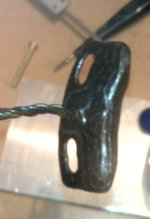
Well, in my application, I setup extremely good active cooling on my HXT motors. I went through a lot of effort to enhance the cooling potential of the motors to the max, so I would not expect this level of power handling from motors just bolted up to some steel brackets etc.

I lapped the anodization off the face on a machinist flat block with 600grit paper, then went down to 1000grit. Then mounted them to a lapped flat surface on a 1/2" plate of 6061, and mounted giant CPU heatsink with a thermostatic controlled fan on each heatsink that kicks on if the base of the stator reaches ~170F. The fans have only turned on a few times total that I'm aware of over the whole time I've had the bike. You gotta power up a very long hill with the pair of 18FET Methy controllers at 50-60mph to get the motors hot, and that's dumping 8,000-10,000watts into each motor. In my application, the controller heating is still the weak-link before motor heating.

That's my real-world experience with the big HXT motors. :)
 
Burti,gwhy,

How potent is your starting tourque witht your halls at 17.14?

I have reserected the 1st of my blown mini controllers tonight.
My motor is running dead smooth, & will just start ticking over at low throttle with out any issuse. But it seems my starting tourque is weaker than my expectations.(may be the reason for the failures?) My only test run had a nice downhill starting run & was prolly forgiving to the cntroller. In ohio I had no such luxury.

I can apply load to the can with one finger & the motor will not start. just shakes & grumbles. Once up to 150rpms I cant stop it. (need to get working on the dyno again)

I know gwhy launches like a crazy man with his trial's set up. (I assume it takes some tourque to break a freewheel).

I guess Im just looking for a little insight.
gwhy, what is your favorite programing settings on your 116 chip 6fet?
Right now the best performance (on the bench) looks like

phase current=55
batt curent=30
block time=3
limitspeed setting=99
cycle mode
speed1=100
speed 2=120%
speed3=100
(IIRC the switch setting is what activates speed 1&3)
I have my shunt soldered on both legs.
Any thoughts on if the 80mm motor is just too much for these tiny tot's?
Thanks for any input. T
 
Hi Thud,
When I had the external 17.14 degree sensors fitted to the big HXT on my stinky, the starting torque was very strong and controllable. It was one of the things that impressed me most about the sensored setup.

If your starting torque is weak but it runs well at speed, this might indicate that your phase current limit is set too low,
or that the sensor timing is set too advanced.

I think the 6 FET controllers may be a little undersized to get the full potential from the big HXT, as this motor will easily draw 120 amps of battery current on a regular basis if allowed to.

Burtie
 
Hi Thud,
Like Burtie have said the startup torque is huge and yes this is what broke my freewheel hub but this was with a smaller 3250w motor ( I havent used my big motor on a e-bike as yet ) Looking at your settings I would also say that your phase current is lower than mine I think ( from memory ) my settings on the 6fet is
phase current=55
batt curent=20
block time=1
limitspeed setting=99
Switch mode
speed1=20
speed 2=100
speed3=60

And programmed using the 18fet software. The shunt legs are both soldered but I also have a addition paralleled shunt ( tiny value :?: ) on the other side of the board. These setting give me a battery limit of around 70A running on 48v ( I will take some pic's of the shut when I get the chance ).
So was your controllers ok but just didnt have enough torque to pull away ? or did some give way with them.
 
Burtie said:
KiM
Dont be afraid of fitting hall sensors to your motor. If you dont mind just glueing them in the stator slots, which works well on my Stinky, it would be a very easy job for you to do (considering some of the amazing stuff I have seen you produce in the past :shock: 8) )

You usually need to take these Turigy motors apart to fix the bearings anyway!

Go for it.
Burtie

Yes, you, based on my experience with one Turnigy 6374, can even run them edgewise. I was surprised when I noticed that the Hall sensor would work pretty much regardless of where I passed a magnet over them when I was playing with Fechter's Hall tester. So, I thought what the heck and they worked.

There's a picture in this post.

Larry Barefield
 
Back
Top