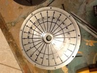
Air Cooling my x5

In terms of physical winding temps, I didn't notice any major impact with drilling a bunch of holes. The motor covers run cooler, but the windings still get awfully hot.

It didn't increase winding temp, and now I can easily smell the hub cooking when its hot, so its better than nothing.
I've been considering drilling a bunch more holes and throwing a high CFM fan on the outside.
 
Well if it isn't hurting, then its helping. I get a different result, and I have just perimeter holes too. 3/4" diameter between each support rib, placed over the windings. Seems to help quite a lot with keeping things cooler, and cooling down quicker. I agree though, that you can smell some of the outgassing when the motor gets warm. Also, the motor seems a bit noisier now.
 
can I ride my bike in the rain with these holes? snowy winter weather?

It can't be hard to make covers for bad weather... which I will probably do. I might try putting some steel on the other side of the motor cover so I can put a big flexibly magnet over the motor
 
My motor never had any issues in the rain. Unless you like riding in deep water, or hit tons of deep puddles, it shouldn't be a major issue.
Its probably fine in snow as well. Sliding and spinning around in deep snow might force some in the motor, but its not an issue unless you have a bit of liquid sitting in the motor for a while and it rusts bad. Generally the motors you are drilling holes in are running hot, so a little moisture will tend to evaporate.

The motor won't care about running underwater. It wouldn't be a bad idea to ensure the hall sensors have no exposed leads, and that the motor never sits with water inside it. If it really gets a lot of water inside, try to get most of it out, and lift the rear tire and set the cruse at a low speed while drying it out. You're just trying to avoid getting the halls wet, or rusting the motor sized.
 
Salty water from road salt + exposed wire connections inside a motor (phases and halls) sounds like potential motor death to me that is likely to take the controller down with it. Pick up an extra set of covers to put on for the winter would be the way to go.
 
Something that dawned on me recently is that the big chunks of copper exposed due to the overlapping winding strategy of the old style Crystalyte motors makes air cooling far more effective than with newer style motors. It's all about surface area when it comes to cooling with air and the artwork of windings on these motors leaves many times more copper surface to be exposed to the airflow. That end copper may be a detriment to efficiency, but it's a great copper heat sink for the enclosed windings.

Another beneficial aspect is the angled stator slots, which will definitely help get air flow through the gap, so be sure to consider the directional nature of this and take advantage of it in your air flow strategy.
 
Well this was a good informative thread of interest to all, but no posts for a while did some new air cooling tech make it obsolete, or is the new Crystalyte ht/hs models stealing the limelight. John did you finish/ test your 9c , im still keen on these as they can be half the price of a ht/hs and with good cooling should be able to handle good power.
 
Emoto said:
Well this was a good informative thread of interest to all, but no posts for a while did some new air cooling tech make it obsolete, or is the new Crystalyte ht/hs models stealing the limelight. John did you finish/ test your 9c , im still keen on these as they can be half the price of a ht/hs and with good cooling should be able to handle good power.

The 12fet high voltage controller fried before the first ride, and the 18fet fried after the second short and mellow test ride, so never enough to put the cooling to the test with the 9C. Since the motor has no spoke flanges it's just on the shelf while others be the high voltage guinea pigs. My son and I have refined the approach with other motors, which has worked great. One is the equivalent to a 2 turn HS40 if Xlyte made one, and my 175lb son bombs up steep mountain roads at up to 167wh/mile performance with just a warm motor at the top. I blasted most of the way up one including accelerating up the 30% grade section with Hubmonster pushing my 90lb SuperV and 260lb me. I turned around due to a battery shortage after a solid 2.5 miles of constant climb, and Hubmonster was cooler than his motor.

Hubmonster has a slightly different approach with intake only on one side and exhaust a the extreme perimeter on the other, and fan blades in both covers right at the windings. The in one side and out the other is an attempt to get more flow across the stator. It worked but the intake side is slightly warm and the exhaust side near ambient, so I need to tune it a bit by blocking much of the open space in the stator spokes. Too much flow is taking that path of least resistance. The stator is 50mm wide, so much more surface area than either side, so I believe directing half of the air flow through the magnetic gap is good goal.

I took pics and will fully disclose all the hows, whys, and results in a new thread in the pics and video section very soon. Unless the oil cooling guys add significant outside surface area, they'll never get to the performance level we're seeing with a well planned centrifugal air cooling strategy. I'm not talking about the typical holes in a pizza pan approach so frequently used which has marginal benefits.

John
 
Hopefully your data will include empirical evidence like actual temperatures & temperature changes, not just "warm", "warmer", "better", etc...
 
itchynackers said:
Hopefully your data will include empirical evidence like actual temperatures & temperature changes, not just "warm", "warmer", "better", etc...

Sorry, but I've never bothered with a temp sensor since I've never burned up a motor. That's despite running faster and with heavier loads than the vast majority who have. A 5mm wider stator is not the explanation. I've done my research homework into air flow systems, and I've crunched the heat transfer numbers. Then I actually try different things and share what works, and share explanation of what doesn't.

I'm into results more than the numbers behind them, and our biggest problem has been creating a big enough load to test the limits of my centrifugal cooling approach, and have yet to get a ventilated motor close to hot. Those who have is due to 2 factors, improper approach combined with pushing motors past saturation. We don't have enough controller to push these low turn count motors into saturation.

Here's some empirical evidence for you though, and far better than simple temperature measurement of one unknown spot on a stator. Through research and calculation, I came up with a reasonably conservative estimate for heat dissipation above 350rpm (about 21mph in the 20" wheels we run) of 2-2.5kw for a common 20cm stator motor using my approach to ventilation. At 75% assumed efficiency under heavy load, that's 8-10kw input. The most we've managed using a steep 3.75 mile hill and some extra weight in a backpack is to push 1kwh through the motor in right at 7 minutes. First we rode around for a couple of miles with plenty of hard launches to make sure the motor was at a decent operating temperature before attacking the hill. The motor wasn't noticeably warmer at the top of the hill than at the bottom, and after a 2min wait it didn't feel any warmer, so there wasn't a lot of heat stored at high temp in the stator. That 8500W average input with the far heavier load in the top half where it's much steeper, proved to me that my calculations and estimates were valid and on the conservative side, though we still don't know the limit.

FWIW, I also came up with an estimate for the oil bath approach of a sealed DD hubbie using the same methodology, and even with covers reaching 100°C (a temp I don't want my magnets reaching), the max heat it could dissipate was less than 1000W. No doubt that it would be helpful for those running less than 4kw average with higher turn count windings and pushing the stator into saturation in short bursts or other intermittent low efficiency situations, but not for the continuous power I require to tackle long steep hills or to hit highway speeds in excess of 60mph. More surface area or some kind of radiator is required.

John
 
Good to hear your still motivated and evolving the design :idea: , as im convinced this is way. no wires/ fans/ oil, especially easy for manafactures to implament at a low cost.
I still might go the 9c with centrifugal air cooling max 4kw , rather than a hs/ht.

I took pics and will fully disclose all the hows, whys, and results in a new thread in the pics and video section very soon

Awsome, i think a important point would be to provide a before and after mod results as a referance [ i know its more effort ]
im sure you know there would be many members wanting to do this mod, but hesitant before drilling that sucker! out.
 
Emoto said:
Awsome, i think a important point would be to provide a before and after mod results as a referance [ i know its more effort ]

I can do better that that. I've got identical motors in the same size wheel running the same voltage, one sealed and one ventilated. Even when we load the ventilated one down much heavier, it's always much cooler, including the telltale spots (between the spoke flanges and at the axle). Sometime we'll bring along a thermometer and video for the doubters. That will calibrate my fingers, so I get some benefit too.
 
Yes, please shoot the windings on the ventilated one, not the cover, as the difference between the two can vary greatly (and with different style motors).
 
John in CR said:
icecube57 said:
Would scoops like this help force air into the hub.

No. Jeremy did a calculation in the other thread.

I checked Jeremy Harris's calculation. He got it right: At 30 mph, a scoop 4'' from the axle on a 26'' wheel would generate a pressure of 0.027 psi when facing forward. He concluded that scoops aren't worth the effort because this is such a small pressure difference. However, he didn't actually calculate the pressure difference achievable with a hub turned into a centrifugal fan. I did that, and found it to be even lower!

Here's the scoop (pun intended):

For the scoop, the pressure difference is 1/2 * rho * v^2, where rho is the density of the air, and v is the velocity of the scoop with respect to the outside air rushing by (taken as the velocity of the scoop w/r to ground). For the centrifugal fan, take a cylinder spinning at angular velocity omega. Assuming, for the present purpose, that air is incompressible (since the pressure differences are so small), the pressure inside the cylinder is P0 + 1/2 * rho * (omega * r)^2 where P0 is the pressure at the axle, omega is the angular velocity, and r is the distance from the axle. In other words, the pressure difference is also given by 1/2 * rho * v^2, except here the velocity is the velocity of the exit hole with respect to the axle (assuming the intake hole is right at the axle).

The ratio of the two pressures, for a 26'' wheel (radius 13'') and an intake scoop (or exit hole for the centrifugal fan) 4'' from the axle is thus p_scoop / p_cent_fan = (1 + 13/4)^2 ~= 18. This only depends on where on the hub the hole is, not on the speed, which cancels out. Since the air flow rate through a hole is proportional to the square root of the pressure difference, the scoop concept will produce an air flow that is (1+ 13/4) = 4.25 times greater than the centrifugal fan concept. In other words, scoops cool roughly 4 times more efficiently than centrifugal fan blades, for the same size holes!

(We might want to divide this number by 2 since only about half the scoops are facing forward at any given time. However, the centrifugal fan efficiency is also less than calculated since (i) the intake holes are at some distance from the axle, and (ii) the stationary stator inside the hub prevents the air from spinning at the same rate as the wheel. So advantage: scoop!)

In the scoop design, the intake holes are covered with scoops and should be as far from the axle as possible. Separate exit holes are not needed since the scoops, when they face backwards at the bottom of the orbit, serve as exit holes. However, in order to get air from one side of the motor to the other, it might make sense to drill a set of exit holes on the other side (w/o scoops).

I am working on implementing this on my hs3540. 6 scoops will go under the brake rotor, forcing air into 1.25'' holes. Will post pictures and temperature measurements as they become available.
 
I came to the same conclusions. The pressure generated is negligible. Be prepared for John to tell you that you're a big idiot and his way is the only way. I'm still waiting for some tangible data on his motor temps. I hope he comes through.
 
itchynackers said:
I came to the same conclusions. The pressure generated is negligible. Be prepared for John to tell you that you're a big idiot and his way is the only way. I'm still waiting for some tangible data on his motor temps. I hope he comes through.

Just you. If someone thinks like you do, that air will get "scooped in" or pulse in at the top and out at the bottom through holes at the perimeter of the motor, they are misguided.

If the scoops are closer to the axle than the exhaust holes, so the flow isn't fighting against centrifugal force of the already spinning air, there's nothing wrong with that. If I wasn't concerned about sand and dirt getting scooped in, then I'd have scoops on the intake holes too like H.H plans.

The missing part in H.H's analysis, is that the exhaust holes aren't the blades, because both side covers are the "blades" that get the air spinning. The air inside is spinning even if the motor were sealed, and exhaust holes at the perimeter and intake holes at a lesser radius allow fresh air to come in and flow out. If shape the exhaust holes incorrect the resulting turbulence from the exterior influences will choke the flow as DocBass found out when he got his left and right mixed up when angling his holes. He ended up with scoops at the perimeter and a hot motor as a result.

Where most go wrong is with exhaust hole placement and sometimes no intake holes at all. Without intake then obviously no flow can occur. If you put the exhaust holes at the same radius as the windings, where is the flow going to go, over the windings, or just hug the smoother side cover and out the hole, kinda like blowing to the side of your cup of coffee instead of into it to cool it off?

Is it a tremendous flow? No, and that's why I go to the extra effort to install actual blades inside the side cover, which serve multiple purposes. It directs the flow away from the side cover, and creates more turbulence directly at the end-windings for a higher convective heat transfer coefficient. The blades also ensure that more of the air is spinning at full motor rpms.

I'm sure my approach is far from ideal, but it works well enough to not overheat motors at continuous power levels that cause others to fail, so Itchynackers, instead of sitting in the corner scratching your balls and posting idiotic comments, why don't you come up with something better and test it yourself instead of relying on other to do all the work for you?

John
 
quod erat demonstratum

Once again, blanket generalizations. Anyway, I do have 4 motors John. One sealed, one ventilated, one liquid cooled, one 5404 in a box. So I'm pretty sure I've covered a few cooling techniques. And guess what? I actually HAVE temp sensors on 3 of them! None of them have melted either! Amazing. I suppose your response would be, "then youre not pushing enough watts, like me". Everyone here appreciates your efforts. I would suggest being a bit more diplomatic in your responses.

Oh, and I'm pretty sure every male here has scratched their balls. Be honest with yourself!
 
John in CR said:
Emoto said:
Awsome, i think a important point would be to provide a before and after mod results as a referance [ i know its more effort ]

I can do better that that. I've got identical motors in the same size wheel running the same voltage, one sealed and one ventilated. Even when we load the ventilated one down much heavier, it's always much cooler, including the telltale spots (between the spoke flanges and at the axle). Sometime we'll bring along a thermometer and video for the doubters. That will calibrate my fingers, so I get some benefit too.


Well thats a serious aproach man, removing close to all variables nice, later i can see you getting requests to fit temp sensors to the windings on both , look forward to the new thread.
 
2 things to remember is the bottom of the wheel doesn't move it is locked to the ground so centrifugal forces are not like normal and the other the rpm is LOW my bmx with a 20" wheel (lower rpm with a bigger wheel) only spins 800 rpm at max speed (85km/h) BUT the problem with heat is 0-20 km per hour and I am doing 0-20 all the time to have fun with wheelies so the rpm is 0-~200rpm so for an average of 100 rpm how much air will flow when the bottom holes in the wheel are not moving in relation to the air outside the wheel and the holes at the top are. I had great success with forced air and it uses a low amount of wattage. But If I continue with hub motors I am planing to either add more forced air like an external ducted fan or a spray of watter or oil.....
 
Arlo1 said:
2 things to remember is the bottom of the wheel doesn't move it is locked to the ground so centrifugal forces are not like normal and the other the rpm is LOW my bmx with a 20" wheel (lower rpm with a bigger wheel) only spins 800 rpm at max speed (85km/h) BUT the problem with heat is 0-20 km per hour and I am doing 0-20 all the time to have fun with wheelies so the rpm is 0-~200rpm so for an average of 100 rpm how much air will flow when the bottom holes in the wheel are not moving in relation to the air outside the wheel and the holes at the top are. I had great success with forced air and it uses a low amount of wattage. But If I continue with hub motors I am planing to either add more forced air like an external ducted fan or a spray of watter or oil.....

You're absolutely right that a passive ventilation approach won't help at low speed. The time I tested one with smoke it only started suck smoke into the intake at about 10mph, about 150rpm with the wheels I use. For a forced air setup, what you need is a hubbie with a drum brake, because it gives you a large stationary cover relatively sealed to the spinning side cover. I couple of 2" ducted fans will fit easily.

Regarding the exhaust holes movement relative to the outside environment, my strategy is to minimize it's effect. The air inside is spinning relative to the inside of the hub, and no different than a tire gets skinnier all around if it spins fast enough on the stand or going down the road, the centrifugal force on the mass of that spinning air will push the air to the perimeter and out the exhaust holes throughout the rotation. The complex nature of the holes' movement relative to the environment is why I've never tried proper blades outside of the exhaust holes. Plus, that route is guaranteed to make plenty of fan noise.

John
 
hey guys,
I had to open my HS3540 to fix hall problem, figured while im at it id drill some holes for air cooling and water. Im not running 100V 100A + like alot of you, just 18S4P of lipo, still figured if im making holes for water I may as well make them efficient for air cooling as well. Since im not running as much power as you guys and wont be anytime soon, im not bothering with blades and such. Just want to get some opinions if this will work well for me (picture below) Ill hold of on drilling till i get some feedback, dont want to weaken cover to much and want to make sure hole size and number of holes seems appropriate.

Inside perimiter circle every even number 1/2 inch holes 12 holes
and 24 1/4 inch holes outside perimiter (little lines)
Ill be angeling holes on inside perimiter to intake air and angle outer holes in opposite direction to throw out air.
Same for both side covers.

cover holes.jpg

Thanks for any input
Fred
 
Back
Top