Axiom: a 100kW+ motor controller

I am following this thread with bated breath! A big power VESC that can handle serious real EV voltages is a game changer for EV performance.

Just throwing this out there: One of my companies does CNC machining, silicone gasket making, and automated potting. We are in Reno NV which is a desert haha so great conditions for potting. We would be happy to help with this project!

- Brad
 
liveforphysics said:
I recommend molecular sieves sized for water vapor pore diameter.
https://www.impakcorporation.com/molecular-sieve-is-the-best-desiccant

this is the sort of things we're brainstorming right now so thanks for the input. another example, say you ship a controller to client but customs opens the box AND motor controller for inspection. that's a sealed lid.

there's lots of little things like this which makes production 1000x more difficult than prototype. one step at a time though
 
Braddudya said:
Just throwing this out there: One of my companies does CNC machining, silicone gasket making, and automated potting. We are in Reno NV which is a desert haha so great conditions for potting. We would be happy to help with this project!

thanks for the offer Brad, much appreciated.
 
just doing some simple testing. no coolant flow at all.. running 150A and we see a 2 degrees rise and well balanced temperature spread. we put a flatness spec on the IGBT area and proper application of paste helps. its a heavy enclosure but we optimized to put thermal mass in the area where we need it so that we can handle burst power application better. its not a wimpy heatsink like the commercial one we were using for early day testing. the thermal mass has other benefits, helps smooth out the temperature bumps giving the temp sensor a better opportunity to measure without an emergency power cutback.

so far so good.

FYI, we're not as much testing the controller as we are testing the enclosure. the controller we already tested last year.
 
On the post Apr.11.2019, by marcos it says

"PowerDesigns should provide the assembled boards to anyone interested. We can offer bare PCBs on demand but the risk is so high and I didn't see a successful build when people have to assemble the boards, so its better if we take care of the assembly. Its even much better if we provide the complete motor controller, we are working on providing that option."

So what im wondering about is the part about "Its even much better if we provide the complete motor controller". So what is missing from the gerberfiles to make the "complete controller". I have seen this controller running the nissan leaf engine, 80kw. But does this axiom controller replace the nissan leafe controller and inverter? Can I connect this axiom controller directly to the nissan leaf engine, I bellive its an 80 kw dc bldc motor, not sure if it uses hall sensor or something else, and controll it? attach it to the nissan leaf transmission and run the car?

I think the nissan leaf battery is 200amps/400volts, does it support regenerative braking, PID speed controll, cruise controll, and all the other features in the open source vesc software? Am I supposed to use some of the parts from the nissan leaf inverter to make this controller? Or how would I be able to create the complete controller on my own, even tho you dont recommend it?
And does it support charging from shore power, 240v ac or 120v ac?

I bellieve I found the correct gerberfiles?
https://paltatech.com/files/ibom.html

and the schematics top lvl, but it lack some parts for the complete controller?
http://www.powerdesigns.ca/wp-content/uploads/2019/04/VESC-controller.svg_.png

Does it exist any documentation on the schematics, how upload the logic to the board etc?
 
the gerber files you link to are old and contain errors. i would not recommend you use it.

We are using AXIOM to drive a leaf motor, literally as i type this AXIOM is pushing 800A phase current into a leaf motor with no liquid cooling for 10 seconds (at which time the IGBT is recorded at around 80degC)
also to answer your question.. the gerber file is just the control board (out of date and not recommended for use as it contains errors). AXIOM is a motor controller unit so it contains not just the control board, but also the IGBTs, gate driver, current sensor, copper busbar, DC link capacitor, liquid cooled heatsink, power connectors, CNC enclosure from a single block of aluminium
 
found a part that was susceptible to the high ambient temperature that occurs when you put a lid on your enclosure. part doesn't fail, its rated for 150deg, but its performance drifted out of spec at the high end causing an overall limit to performance. not acceptable!! took a while to find the offensive part scanning the board with a targeted hot air gun... but we found it. as hot air gun was overtop the part the signal running through it would drive from centered on 1.65V to centered on 1.66, then 1.67, then 1.68..... until it was out of spec and tripped a shutdown at around 85degC. honestly, its a pretty rare day when ambient temperature inside controller is that high but we're going for max performance and so we make the effort.

FYI, we tested both VESC sensorless algorithms (original ortega and mxlemming) at 200A phase current and its smooth as butter, very nice. haven't tested these at the much higher amps yet but we will.
 
we're going for max performance and so we make the effort.

Still perfecting and testing the controller(y)
Are there any real world projects where this controller is used in already? Any links to builds or video's we can watch or follow?
Would love to see what this controller is capable of.
Keep up the good work!
 
found a part that was susceptible to the high ambient temperature that occurs when you put a lid on your enclosure. part doesn't fail, its rated for 150deg, but its performance drifted out of spec at the high end causing an overall limit to performance. not acceptable!! took a while to find the offensive part scanning the board with a targeted hot air gun... but we found it. as hot air gun was overtop the part the signal running through it would drive from centered on 1.65V to centered on 1.66, then 1.67, then 1.68..... until it was out of spec and tripped a shutdown at around 85degC. honestly, its a pretty rare day when ambient temperature inside controller is that high but we're going for max performance and so we make the effort.

FYI, we tested both VESC sensorless algorithms (original ortega and mxlemming) at 200A phase current and its smooth as butter, very nice. haven't tested these at the much higher amps yet but we will.
Guessing opamps? on current sensing or resolver?

Anyway... When you run the observers at high current, could you have a look out for their deviation from the encoder angles if that is easily available? (resolver is more problematic since they often have their own lag/compensation whereas incremental encoder is basically always correct). The observers are not really designed to work with highly salient motors, and we have had some suspicion that there is an error associated with that at high currents (they have no way to differentiate between back EMF resulting from permanent magnet flux and from reluctance flux). So far, no one has been able to produce definitive evidence that this is a significant problem, or a problem atall. There are a few hypothesised candidate solutions (I have coded one already) though if there is a problem.

Without the solution, it appears that the effect (with flux linkage compensation) might be to align the reference frame with the MTPA angle, thus rendering MTPA... incorrect... but still working fine. Except with hall sensor transition.

This is all rather hypothetical though. At the moment I have no motors salient enough to really test this.
 
good guess, we thought it was the resolver op-amp. we like 99% sure. but the math said it wasn't that bad and also the part itself is operational at 150degC (hard to believe). so we tried some other op-amps and all the same. although, in our search we did actually find a better opamp so that was good. but .. alas, it was transient protection diodes with too high leakage current.

leaf motor is highly salient. actually we have to run a lot of D-axis current at higher loads to be able to reach peak performance (i.e. in excess of 800Arms phase at 400Vdc bus). its why we got into MTPA algorithm early, though i see today vesc uses a much simpler version than what we submitted few years ago. vesc algorithm will have an issue with rapidly declining duty % when MTPA is being used. we will eventually get to testing sensorless at the high currents because although we don't use it (we like the reliability of a resolver for motor position) it is actually very handy to have for test purposes sure, but also for a limp home emergency mode.
 
Still perfecting and testing the controller(y)
Are there any real world projects where this controller is used in already? Any links to builds or video's we can watch or follow?
Would love to see what this controller is capable of.
Keep up the good work!

there are some early day prototypes out there being used privately with not much in the way of publicly available build logs.
the modern version of AXIOM (rev2) with liquid cooled integrated heatsink, we haven't shipped any yet as we are still in the process of testing it. lots and LOTS of interest though, so that's encouraging. we built up the first 2 complete units (photos are posted in this thread history) and we're putting it through the paces to find any bugs or whatever (such as transient protection diode with too high leakage current at ambient temperatures above 80degC), then we'll collect up all the test results, modify the two boards we have .. actually we'll modify all 10 we have on hand now, and then up-rev the official schematics to Rev3 and proceed from there.
 
good guess, we thought it was the resolver op-amp. we like 99% sure. but the math said it wasn't that bad and also the part itself is operational at 150degC (hard to believe). so we tried some other op-amps and all the same. although, in our search we did actually find a better opamp so that was good. but .. alas, it was transient protection diodes with too high leakage current.

leaf motor is highly salient. actually we have to run a lot of D-axis current at higher loads to be able to reach peak performance (i.e. in excess of 800Arms phase at 400Vdc bus). its why we got into MTPA algorithm early, though i see today vesc uses a much simpler version than what we submitted few years ago. vesc algorithm will have an issue with rapidly declining duty % when MTPA is being used. we will eventually get to testing sensorless at the high currents because although we don't use it (we like the reliability of a resolver for motor position) it is actually very handy to have for test purposes sure, but also for a limp home emergency mode.
I'm not understanding how it was made simpler. It looks pretty much identical, just it's been inlined with the foc loop and this the variable names changed.

Your original commit:
It's now:

There's discussion about the complication of combining with field weakening in the commit.

How will the current implementation result in rapidly declining duty? If there's duty left over then one of two things happen... It can spin faster or it will sit at the MTPA setpoint generating torque against a load.
 
sorry, i'm talking about field weakening. the MTPA algorithm we made still works pretty good. but FW, i think the algorithm that showed up in VESC is not the version we submitted. what is in vesc is some sort of linear approximation of Id with respect to duty%. Also, just a side note, be careful about VESC use of the word "duty" it is not the same as is traditionally used in motor control theory. in motor control theory, duty just means for the PWM the percentage of ON time with respect to the total period (1/fsw). but vesc uses "duty" to mean something else.
FW has an issue with rapidly decreasing duty (traditional definition). i think the algorithm we originally submitted will not have this problem but haven't had a chance to test it.
 
be careful about VESC use of the word "duty" it is not the same as is traditionally used in motor control theory. in motor control theory, duty just means for the PWM the percentage of ON time with respect to the total period (1/fsw). but vesc uses "duty" to mean something else.

it refers to the reference vector magnitude, right ?
 
it refers to the reference vector magnitude, right ?
Seems to refer to the ratio of mod(Vq, Vd) to the max duty possible. This should result in a similar number to the max pwm on time but using the raw pwm duty will result in strange jitter due to the svpwm algorithm. The VESC way of calculating it is sensible IMO from a user perspective.

The field weakening, I looked into that and :s high hopes is right. It could have strange effects. Industry standard is to use a "closed loop" controller, that is effectively you ramp up the field weakening (often by PI) when the duty hits the max limit and back down when it's below. That way for a range of speed you have a constant max duty.

I tried both, the industry standard way is comprehensively better.
 
Seems to refer to the ratio of mod(Vq, Vd) to the max duty possible. This should result in a similar number to the max pwm on time but using the raw pwm duty will result in strange jitter due to the svpwm algorithm. The VESC way of calculating it is sensible IMO from a user perspective.

Since mod(Vq, Vd) = mod(Valpha, Vbeta), isn't duty effectively same as reference voltage vector magnitude (max limited)?
 
ratio of mod(Vq, Vd) to the max duty possible. <-- yes this is what VESC uses as "duty".. but i think that is mislabeled, maybe should have been called "modulation index" (Ma). its pretty close to duty, but not quite.
why split hairs like this at all? mostly it is convention, so that we can use words like "duty" and we all agree on what it means and don't have to define it every conversation. but for me it matters because eventually you have to do things like prove control algorithm stability and that's confusing to do when the algorithm is written/defined differently than the math. now i have to go change all my math :(
 
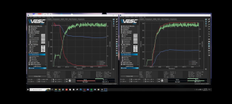
here is a link to AXIOM being tested at the higher temperatures.. arbitrarily setting thermal cutback to begin at 85deg i think it was and then heat the radiator so the liquid "cooling" is hot AF. doing it this way gives you a realistic test and also a stress test at the same time. Its pretty high ambient temperature when the enclosure lid is on and running 600amps through IGBTs on an intentionally very hot heatsink.

 
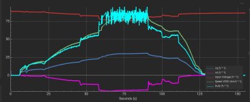
I notice you have quite a lot of noise on duty cycle as well. I'm struggling to understand why. I was trying to work it out for someone with a flipsky (pic attached, it's worse than yours
). Even though Vd and Vq are super smooth the duty cycle is all over the place.

It's not a super important parameter, don't think it's used much (in field weakening calcs?) but it is really odd to me that a value calculated from stable values is so rough.

Since mod(Vq, Vd) = mod(Valpha, Vbeta), isn't duty effectively same as reference voltage vector magnitude (max limited)?
Yes, normalised to 0-1 scale, but it's not quite the same as pwm duty because of the svpwm output shape. Pedantic but I think I also prefer the modulation index term, though that's a bit of a tedious name in code.
 

Attachments

  • Screenshot_20230418-080935.png
    Screenshot_20230418-080935.png
    516.8 KB · Views: 13
  • IMG-20230416-WA0001.jpg
    IMG-20230416-WA0001.jpg
    64.8 KB · Views: 14
noise on duty cycle .. it moves around a lot, but its not necessarily because of noise. could be that is how fast duty has to change to maintain the current command. its hard to tell
 
I notice you have quite a lot of noise on duty cycle as well. I'm struggling to understand why. I was trying to work it out for someone with a flipsky (pic attached, it's worse than yours
). Even though Vd and Vq are super smooth the duty cycle is all over the place.

It's not a super important parameter, don't think it's used much (in field weakening calcs?) but it is really odd to me that a value calculated from stable values is so rough.


Yes, normalised to 0-1 scale, but it's not quite the same as pwm duty because of the svpwm output shape. Pedantic but I think I also prefer the modulation index term, though that's a bit of a tedious name in code.
Uhm. Duty cycle is not actually duty cycle. Its a calculation of something it jumps to negative duty at times. So I have not worried a lot about it but I do look at it as when its a cleaner signal it seems to run smoother.
 
This thread is wonderful, I'm newly but closely following this project.

I tried searching the thread but wasn't getting any results - are there known vehicles that use the 600a 1200v IGBT modules (FF600R12ME4WB73BPSA1 I believe)? Or really any of the infineon modules. I'd love to pull some from a junk yard to use in the early stages of experimenting with IGBTs, so I'm not losing $350 a pop if I break a module 😅. If that info doesn't exist I'll try to start researching and putting together a list of cars-we-can-pull-parts-from.

I'm very excited to see this project, thanks for putting the time into such a great open source project.
In 3+ years of testing I have never had a single module fail. The safety built into Axiom is amazing!
 
Back
Top