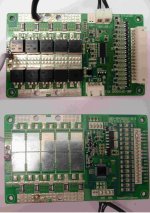
bluetooth BMS?

respire said:
For those who use the the BMS compatible with the Xiaoxiang app, have they successfully tried alternative apps?

The reason I want another android app is that I find it too slow to startup as it asks me to change my GPS setting every single time.
I just leave my GPS on, and have "no permissions granted" to the xiaoxiang app, and it starts up fast for me without asking for my location.

I also don't trust the chinese app permissions to my location, even though it might be able to calculate watt hours per mile, which would be nice.
 
Duranza said:
Anybody tried to see if the LCD text can be translated to English?

I went round and round with various sellers of these BMS and the LCD not being 100% English. I was told to buy to BMS and LCD, but that it would not be fixed. They were unwilling to deal with the manufacturer to get it fixed. IE: This is pretty typical of Chinese made products that are converted to Western users. You get some stuff fixed for English and some stuff...not so much. So much stuff out of China is done only because it's cheaper. Fixing things like the LCD costs money so no one over there is going to do anything.
 
Lost track of what all has been posted about the 15s bt bms. Today I finally had time to connect an lcd display.
Mostly Chinese so it sucks, but if you want a simple cell monitor on a switch and no bt. it does work.


Shown on 12s Volt. Arrows indicate H and L cells.
Better than a poke in the eye I guess!
 
I have one of these smart BMS from RJXZS. I am using the JBDTools software. I have hooked up an on-off switch to the BMS and it's working fine. But when I plug in the charger, the discharge FET's switch on. (the charge FET's is switched on all the time) Is there any way to config it so the output remains off when I charge?
.......
On second thought, I think it was a dumb question when I look at the BMS layout :oops: It appears the charge FET's are placed behind the discharge FET's, so for it to charge, the discharge FET's has to be switched on too, right? Is there a similar BMS on the market where you can switch off the discharge port, and still be able to charge it?
 
Longlight said:
I have one of these smart BMS from RJXZS. I am using the JBDTools software. I have hooked up an on-off switch to the BMS and it's working fine. But when I plug in the charger, the discharge FET's switch on. (the charge FET's is switched on all the time) Is there any way to config it so the output remains off when I charge?
.......
On second thought, I think it was a dumb question when I look at the BMS layout :oops: It appears the charge FET's are placed behind the discharge FET's, so for it to charge, the discharge FET's has to be switched on too, right? Is there a similar BMS on the market where you can switch off the discharge port, and still be able to charge it?

Discharge or P- mosfets should be on 100% of the time except if you over load or run the cells down too low. C- or Charge mosfets should be on 100% of the time except if you over charge.

Having said that, Maybe you have the BMS settings wrong for your cell chemistry?

I personally never use the C- mosfets...NOT EVER. I charge and discharge at P-.
 
Longlight said:
I have one of these smart BMS from RJXZS. I am using the JBDTools software. I have hooked up an on-off switch to the BMS and it's working fine. But when I plug in the charger, the discharge FET's switch on. (the charge FET's is switched on all the time) Is there any way to config it so the output remains off when I charge?
.......
On second thought, I think it was a dumb question when I look at the BMS layout :oops: It appears the charge FET's are placed behind the discharge FET's, so for it to charge, the discharge FET's has to be switched on too, right? Is there a similar BMS on the market where you can switch off the discharge port, and still be able to charge it?

How do you expect that to work exactly? If you want current to flow only one way then you could add some Ideal diodes in series.
 
ElectricGod said:
Discharge or P- mosfets should be on 100% of the time except if you over load or run the cells down too low.

But I use the switch option on the board to turn off the discharge FETs when I'm not using the battery. Is that somehow bad for the BMS or FET's?
 
Longlight said:
ElectricGod said:
Discharge or P- mosfets should be on 100% of the time except if you over load or run the cells down too low.

But I use the switch option on the board to turn off the discharge FETs when I'm not using the battery. Is that somehow bad for the BMS or FET's?

Go ahead and switch off the BMS...AKA the P- mosfets if you like...no harm done.
I don't think turning off the BMS really turns it off, but I could be wrong. I think it just turns off the P- mosfets. Proof of that would be if the BT connection works with the BMS turned off or not.
 
If anyone cares...

I've been ignoring the screen lock function on my 16S and 20S smart BMS since I didn't see it did anything. Yesterday, I accidentally hit the lock button and discovered it turns off the BMS. No need for a physical button. Does that work on the smaller BMS as well?
 
I'm pretty sure it does, on the 14s 60a version if that's what you call small. My friend has the apple store app, which looks different, but turned off my bike as a joke on one trip.
 
thundercamel said:
I'm pretty sure it does, on the 14s 60a version if that's what you call small. My friend has the apple store app, which looks different, but turned off my bike as a joke on one trip.

IOS app? Really? I've looked and didn't find anything.
 
IOS app? Really? I've looked and didn't find anything.
Sure search “Xiaoxiang bms“ in App Store. It costs a dollar or so when I bought it. Being actively developed, but does not have all features yet.
 
knurf said:
IOS app? Really? I've looked and didn't find anything.
Sure search “Xiaoxiang bms“ in App Store. It costs a dollar or so when I bought it. Being actively developed, but does not have all features yet.
Hmm. Not in the Austrian appstore. Where're you located?
 
Hello.
I have this BMS:
https://www.aliexpress.com/item/14S-30A-active-bms-2017-new-Li-ion-smart-bms-pcm-with-android-Bluetooth-app-UART/32841020357.html?spm=a2g0s.9042311.0.0.70d84c4dx419sL
Which has been thoroughly examined here.

On first install of the BMS, the 4am (obviously tired) me, pluged the balancing wire (after checking the voltage), B- to battery negative, and... the P- (which is on the top side of the picture/schematics, to the battery positive.
It took me some times to realise that the BMS was shorted the whole time I was trying to connect to the BMS by bt or usb (which failed every time).

I was surprised that nothing went in flames, or even got some smoke, or sparkle.

When I plug the BT, a blue led on the bt board blink once. When I try to connect it to my phone, the led stay on for a few seconds, then the connection fails. USB connection, just fails.
Never seen a led light up on the BMS (if there are some).

Does anybody know which component that might have been damaged, so that I can test them, and change them if needed?
Thanks in advance.

HTB1IREVXEjrK1RkHFNR761SvpXa7.png
 
How do figure that the BMS was shorted exactly?

A reason why your phone might not be able to connect to it could be that you have an outdated version that doesn't support the latest Smartphone firmware.

Here is the latest version: https://shouji.baidu.com/software/24043119.html
 
xmtx said:
Hello.
I have this BMS:
https://www.aliexpress.com/item/14S-30A-active-bms-2017-new-Li-ion-smart-bms-pcm-with-android-Bluetooth-app-UART/32841020357.html?spm=a2g0s.9042311.0.0.70d84c4dx419sL
Which has been thoroughly examined here.

On first install of the BMS, the 4am (obviously tired) me, pluged the balancing wire (after checking the voltage), B- to battery negative, and... the P- (which is on the top side of the picture/schematics, to the battery positive.
It took me some times to realise that the BMS was shorted the whole time I was trying to connect to the BMS by bt or usb (which failed every time).

I was surprised that nothing went in flames, or even got some smoke, or sparkle.

When I plug the BT, a blue led on the bt board blink once. When I try to connect it to my phone, the led stay on for a few seconds, then the connection fails. USB connection, just fails.
Never seen a led light up on the BMS (if there are some).

Does anybody know which component that might have been damaged, so that I can test them, and change them if needed?
Thanks in advance.

HTB1IREVXEjrK1RkHFNR761SvpXa7.png

Sorry to hear about you bms!

I'm just about to w ire the exact same bms and a search led me to this thread.
In the diagram the P- is not even used?
The BMS I have used in the past have been pre wired.
Just wanting to confirm the following..

B- to negative of battery.
C- to charge/ discharge.

Should I connect negative to B- first, then balance wires? Or it doesn't matter which first?
Thanks in advance :D
 
I connected the Balance wires then the B- worked for me just fine.

You can use either P- for discharge or C-. The difference is that you need only two wires soldered on the BMS compared to three wires if you use the P-.

An advantage to using the P- is that the BMS will run cooler because you are not heating up the charge Mosfets when discharging the Battery.
Also when using the C- port for both you can't overcharge the Battery via regen, which can happen if you go down a hill with regen right after charging.
 
knurf said:
Hmm. Not in the Austrian appstore. Where're you located?
Ah no this is in Europe. Maybe it's a limited release then.

This GitHub repo is related https://github.com/smagicld/xiaoxiangBMS

Edit: I read "Australia", sorry.. the app store page is linked from the repo anyway. See if that works better.
Thanks! That did work. Searching led me nowhere, but the direct link made it work!!
Works perfectly fine. May need some polishing, but does all it needs to do.


eee291 said:
I connected the Balance wires then the B- worked for me just fine.

You can use either P- for discharge or C-. The difference is that you need only two wires soldered on the BMS compared to three wires if you use the P-.

An advantage to using the P- is that the BMS will run cooler because you are not heating up the charge Mosfets when discharging the Battery.
Also when using the C- port for both you can't overcharge the Battery via regen, which can happen if you go down a hill with regen right after charging.

Thanks for that :D
 
eee291 said:
How do figure that the BMS was shorted exactly?

A reason why your phone might not be able to connect to it could be that you have an outdated version that doesn't support the latest Smartphone firmware.

Here is the latest version: https://shouji.baidu.com/software/24043119.html

Hello, thanks for your help.

I know it was shorted, because I (at 4am), connected the battery -, to B- on the BMS, and then, the battery + on P- on the BMS.
Instead of wiring the load between P- and Battery +.
That's basically a 0 ohm load, and a lot of amps that should have gone through the BMS, and that, for several minutes, until I realised my screw up.
I know that the BMS is supposed to prevent actual overload, but I'm not sure if it's able to handle a short for several minutes without blowing a fuse.

The seller gave me this link for the application (he is helping me right now):
https://drive.google.com/file/d/1v6VG49Uu4Z5F1PsRAOnk-I47lmR0RsOi/view?usp=sharing

I tried your link, but the error is still the same. It can see the bt device (xiaoxiang BMS), the bt receiver light in blue, but after few seconds, connection to it fails. Same for USB connection with my pc.

I tried shorting the K1 switch, while connecting, but the result was the same.
Do you know which key point I should check for voltage or resistance, in order to identify if it's fried or not?
 
I doubt it is broken even if you kept it shorted for weeks.
That is why the BMS can turn the MOSFETs off and it will keep them off until you remove the short.

An easy way to check would be to measure the Voltage between B+ and C- or P- with a multimeter.

What exactly is the error on your PC?


Also, have you tried disconnecting and reconnecting the Balance wires? Maybe power-cycling it once will help.

Another thing I can think of, it's that maybe you have fewer cells connected than the minimum amount of required cells.
Happened to me when I tried to program the 20-30S BMS with just 12 Cells. The light would blink and it could be seen by the app but I couldn't connect to it.
 
eee291 said:
I doubt it is broken even if you kept it shorted for weeks.
That is why the BMS can turn the MOSFETs off and it will keep them off until you remove the short.
Hi again, alright, glad to hear that.

eee291 said:
An easy way to check would be to measure the Voltage between B+ and C- or P- with a multimeter.
That's what I forgot to tell.
B+ to C- and B+ to P- both start a 24V, and stabilize down at 17-18V after a few seconds.
When I connect a load, even a small one (https://www.aliexpress.com/store/pr...-12V24V48V-Lead-acid/2949143_32821877897.html set a 0A), it drops to 0V.
My battery is 14s (52V).

eee291 said:
What exactly is the error on your PC?

On the pc, there is no error. I can see the device (COM10), but when I press start on the application, it just stalls at "Reading data"
All the info are at 0.
View attachment 1

eee291 said:
Also, have you tried disconnecting and reconnecting the Balance wires? Maybe power-cycling it once will help.

I do disconnect and reconnect the balance wire every time. I know current is somewhat flowing, the BT module light up every time and I can see the BT device.
But got nothing on the leads, and, still can't connect to it.

eee291 said:
Another thing I can think of, it's that maybe you have fewer cells connected than the minimum amount of required cells.
Happened to me when I tried to program the 20-30S BMS with just 12 Cells. The light would blink and it could be seen by the app but I couldn't connect to it.

My BMS is 14s, and all the cells are connected, I double checked the voltage they are all in order.
I get no light on the BMS.

The only thing that could cause problem, is the P- solder touching the back of the mofset, but i guess, theses are supposed to be connected. On the picture, it's the grey cable soldered on the left.

BMS_PCB_low.jpg

I've connected another BMS to the battery, and I could draw 2A on it, so it's working
Thanks again for the help.
 
xmtx said:
I've connected another BMS to the battery, and I could draw 2A on it, so it's working
Thanks again for the help.

I realise that my message was confusing.
I plugged a "dumb" BMS, to the battery, and got the battery working.
I don't want to use this BMS, as I can't set treshold on it, and it won't balance charge as well as the smart BMS.

My goal is to limit the battery between 2.9 and 4V/cell, in order to maximise it's life expectancy. And I also want to be able to easily bypass those settings when I need long range .
 
Back
Top