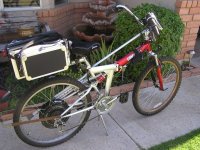
Bonanza "Bulldozer" Dual PhaseRunner AWD

Alan B said:
However I don't think cars running into the rear of ebikes are the main threat.
Still, getting run over even once could ruin your whole day. That scenario scares me more than the rest for some reason. It might be because my normal reaction to the others is to lock em up, lay it down or try to steer around. Your options are more limited in a rear-ender, plus you can't see it coming (although you might hear it - even scarier!)

I think if you are traveling in traffic a blinky light may be distracting without serving any good purpose. Someone following you might block it out then not notice the increased blink rate. YMMV. It would be interesting to hear what others think - jd
 
The one I still have is quite interesting. It has about four slanted tubes that likely have ball bearings rolling, mounted at different angles to detect different deceleration rates. It goes on with the brake, blinking slowly while stopped and faster as well as brighter when decelerating harder. The bulbs in it are 6V and they use PWM so they can make them very bright. It really gets the attention of the driver(s) behind.

It is about an inch tall and maybe 10" wide and has two bulbs, with fresnel lenses, so it casts a beam to the rear.

It is specifically allowed for in the state motor vehicle code. They were tested on cabs in San Francisco and they reduced rear end accidents by a large percentage. The company that made them and holds the patents has gone away, I don't know what happened since. Perhaps the one I have is suddenly valuable.

I think if a light transitions from lazy slow blinking to rapid bright flashing it just "grabs" your attention automatically.

You are right about the rear being a difficult direction to defend yourself from. I'm planning on a good mirror but you can never see that well to the rear.
 
This has been a very good folding ebike for me. You can find it under Ebike photos and videos heading (Evoforce bike build 1). It has a 26" wheels. It would not be a good battery setup for most women because it has alot of top weight. I am used to it tho, and I really enjoy the convienence of being able to put it in my sub-compact hatch or a trunk(boot).P1010121.jpg
 
Finally arrived home from my travels. Hubmotor etc was waiting for me.

Wheel looks good. Well packed. The spokes look a bit stressed due to the angle with this large hub. Guess that's normal.

I took half the Headway pack to a Ham Radio convention this weekend. Folks were really impressed with those cells.

The cogset on the hubmotor is a Shimano Megarange 14-34 6 speed. It looks like the 14T cog might unscrew, but there is not enough thread for a much smaller cog. I'll worry about that later. Hopefully there will be enough room for a 7 cog upgrade.

The direct plug CA has an extra cable, looks like a speedo. I thought that would work through the rear wheel and not need another cable. There is no magnet for it. WRONG. Magnet was in the package.

QUESTION - should I change this for the Cycle Analyst DP with no speedo to save a cable? Thought I was already doing that, they shipped the DPS model. Direct plug to the controller except has a speedo pickup.

The motor controller has the CA direct plug, so that's good.

No switched brake levers either. Guess I'll have to send them an email.

I plugged in the light set to 14VDC. They worked. Taillight, headlight. The mounting looks a bit primitive - cable ties. Is that what folks actually use?
 
Awfully quiet here. No answers I guess.

I ordered a bike stand to work on the bike, a low end Park. Also on order are some 50 amp Anderson connectors. And a mirror. I have some maxi-fuseholders with #6 wire that should work.

Today it is raining here. Makes me think of fenders. Are there any good ones to look for?

I've also been working on specifying the new front wheel / disc brake setup.

Still waiting for the rest of my Headway cells to come (though I have enough to start). Picked up a box at Fry's that will hold four Headway 16AH cells, great for a 12V power or booster pack.

Does anyone have any comment on the Cycle Analyst direct plug with vs without the wheel magnet? Seems to me that using the hall sensors should be fine on a 9 continents, so no real need for another cable/magnet on the bike.

Thanks for your comments...
 
Received the 50A Andersons. SB50's.

Received the side view mirror.

Arranged the swap of the CA. From DP with speed sensor to DP without speed sensor (gets from halls), This eliminates the cable and mounting of a magnet on the spokes.

Ordered the front wheel/disc brake.

The last of the Headway cells have been shipped.

Waiting on the bike workstand and CellLogs.

Going to rain again this weekend.
 
Alan B said:
Does anyone have any comment on the Cycle Analyst direct plug with vs without the wheel magnet?
When I swapped out controllers, I had to solder the pigtail connections to mate the CA. I had some problems, and was never sure what it was. I ended up getting a replacement which solved it. But the point is that the CA and the controller need to be configured together.

Did you say what controller you're getting? In order to display the proper amps, which is one of the primary functions (as 'fuel' guage), you'll probably need to set the CA shunt resistance value. It's a bit of a task, so I'd recommend buying the controller & CA preconfigured together.

This has nothing to do with the magnet speedo tho, but if you someday have to solder a pigtail for it, it's another thing to worry about, unless you had the magnet... But the magnet version is more wires. So that sortof depends on how you feel about wires. And the magnet, etc is another thing exposed to weather... With the magnet version, however, you won't be able to lift the rear tire and go full throttle to see how fast your bike could go if there was no resistance... lol. There may be other advantages/disadvantages but it's too early.

Just re-read your post. What do you mean you swapped CA's? Perhaps I was too late.

And 50A andersons, yeehaw! How many???
 
Thanks for the comments.

I have not shipped off the CA yet, but I'm thinking I will. Saving a wire seems worthwhile though there are quite a few wires anyway. But having to set spacing on the speedsensor and mount the pickup is not very robust or pretty.

I got 10 of the 50A Anderson's that will take #6 wire. They are about $3-4 each. I'm planning to have 24V on each one, so it won't take many - 5 or 6 in my system. I got the red ones so they would not accidentally mate with the grey ones I use for 12V stuff. There is a color code but I'm not following it, unfortunately, due to historical reasons.

I will probably have to calibrate things. I got the controller and CA together but I'm not sure if they calibrated it or not. I do have a WattsUp so I can use that to compare values with the wheel off the ground, perhaps.

The controller is a 40A infineon IIRC.
 
The Park bike stand came in. Of course it is a kit. It is together now.

The front wheel was delayed a bit. Hopefully it will ship next week or so.

The weather this weekend looks bad again, and there are some other projects that need doing, but we should be able to get a few things done on the bike. I suppose the next big step is to put the rear wheel on and start working on the torque arm solution. Check the chain function.

And perhaps assemble some battery/cabling components.
 
Put the Headway packs together. 8 cells in series 16AH for each pack, two packs (one for each side of the rear rack, pannier style).

DSC_5118.JPG


9 pounds 4 ounces for each 8 cell set (cells, plastic spacing blocks, and cell shorting bars). The Harbor Freight case is almost 2 pounds. 11 pounds 3 ounces total, with no wiring (shorting bars are on but no wires yet).

So the whole battery pack system will be about 25 pounds. The cases are a bit heavier than I expected, they feel light.

Ordered the second Cellpro 10S charger a couple days ago, and more balancing plugs.

May get some time and weather tomorrow to start mounting the wheel on the bike and dealing with gears and torque arms.

edit - added photo
 
Mounted the wheel. Having some issues with torque arms.

DSC_5130.JPG


DSC_5133.JPG


DSC_5127.JPG


The dropouts are pretty shallow. The hardware fits well. There is insufficient clearance to get the nuts on the torque arm. It is unfortunate they make the torque arms so short.

Is that disc brake rotating in the right direction? It looks to be in compression rather than tension. The arrow is pointing in the direction of rotation, but perhaps that is not what the arrow meant. The disc on the nine continents is not going to be used, there are no mounts on the frame for it. It is just for stealth to somewhat hide the motor. In these views the bike is upside down and the front wheel is off to the right.
 
Looks like the disc is the right rotation direction; during braking the grip of the calipers would place forces back along the curves of the "spokes" of the disc back to it's mounts, in compression. AFAICR that's how I've seen most discs on bikes and MCs/etc. installed.

If you flip the torque arm 180 degrees, in mirror image of how it is now, would the nuts go on? Alternately, could you use a longer bolt, a spacer tube with thick walls to apply compression to the surface of the arm, and put the nut on the inside of dropouts?

Additionally, you can take the torque washer's tab and bend it down so it is flatter to the axle, so that it sits deeper in what there is of a dropout.

As for whether alloy dropouts will be sufficent, I'd personally rather have a torque plate on there similar to the one someone else recently made, which would actively prevent rotation even if the dropouts failed (and by preventing rotation should prevent dropout failure). Problem about alloy dropouts is you may have no way of knowing if they are already damaged and about to fail until after they already do, as in many cases of alloy part failure I have seen the stress cracks may be under the paint, with the slightly stretchy powdercoating flexing across the crack and not cracking with it, only breaking away after the part has already separated.

Steel bends first before snapping, so you'd probably notice your wheel "felt funny" at high torque before something actually failed. ;) Plus you'd be able to visually see the dropouts spreading, a little at a time, if you check them each ride, if a problem were developing.


What I would like to do myself on such dropouts, at minimum, is make a clamp that goes in a lazy J from the rackmount accessory point then down behind the axle, then forward under the dropout to a clamp or bolt point in front of the dropout somewhere along the chainstay. That might at least minimize the spreading, although with sufficent torque on the dropout it would require it to be a bolt point forward of the dropout, actually welded to the chainstay, to resist the torque. A clamp would probably just slip.

A torque plate that has an axle-shaped hole in it to prevent rotation, that bolts to the dropouts and the hardpoints for racks/etc, even disc brake caliper mountpoints, would be much better, I think.


If you're not going to hit the throttle hard it won't matter, but if you do, the torque can be a lot higher.
 
amberwolf said:
Additionally, you can take the torque washer's tab and bend it down so it is flatter to the axle, so that it sits deeper in what there is of a dropout.
agree. stick the washer in a vice and hammer curved bit down so it lays snug in the groove..

i also feel like a washer is missing between the axle and the frame, last photo. isn't there a fitted washer, not w/ the tab? if so, that should slide up axle till it can't go any further, and the dropout should be outside that.

as it is, it looks like if you tighten the nut hard, it'll make the dropout want to spread over the axle. not good.
 
Thanks for the comments. I agree that it looks like a thin washer should go on the inside. Wonder why they didn't include one. The axle came assembled and the connectors won't fit through the nuts and washers, so it will be some trouble to get a washer in there. It will have to be thin, the dropouts already have to spread a tiny bit to fit. Any suggestions on a good washer for this?

Reversing the torque arms makes the clearance of the bolt much worse.

I ordered a different torque arm today. These don't look too good for this frame.

My Turnigy 8150 chargers arrived today. Received a pair of 6S 6AH Turnigy LiPo for a "light pack" a few days ago. This is for testing, they are small, light and can handle the current.

A spacer tube and longer bolt on the torque arm would work. It would not be wonderful, but it would fit.

I like the idea of a torque plate. Another project.
 
Postman was busy today.

Wheel and disc brake system arrived. Fits! Disc is really really close to the forks at the outer diameter. Forks weren't made for an 8" disc apparently. They don't seem to be touching though.

Need to get rim tape and mount the tire. The nipple hole in the rim looks small, probably have to ream or drill that out.

Waiting on the other type of torque arm. And connectors to match the turnigy Lipos. 4mm shrouded and polarized bullets.

The CA-DP arrived. Lots less cabling!

Should probably start thinking about a center stand for this rig!

Selected some 80V fuses. Have to get them ordered. Lots of details!

Getting close!!
 
Some more progress today. Got rim tape, reamed tube neck hole, installed tape, tube, tire. Realized axle was upside down in reading another thread, bike shop set it up that way, so I flipped it over. Tried to pound the tab on one washer down, not terribly successful. Had to file one side of the tab to clear the derailleur properly. Put it all together just as darkness fell, was able to take it out for a quick pedal-only test. It is working pretty well, need to address some rear brake almost dragging (V brake). The new front Hayes disc brake seems to be working well. The Schwalbe Marathon plus tires seem to be much more efficient than the old knobbies.

DSC_0689.JPG


The lightweight Park bicycle stand is working out really well. It moves around a bit with this heavy bike, but it is really much better than not having one. It stores in very little space. Great tool.
 
GCinDC said:
amberwolf said:
Additionally, you can take the torque washer's tab and bend it down so it is flatter to the axle, so that it sits deeper in what there is of a dropout.
agree. stick the washer in a vice and hammer curved bit down so it lays snug in the groove..

i also feel like a washer is missing between the axle and the frame, last photo. isn't there a fitted washer, not w/ the tab? if so, that should slide up axle till it can't go any further, and the dropout should be outside that.

as it is, it looks like if you tighten the nut hard, it'll make the dropout want to spread over the axle. not good.

I agree with GC about the washer required on the inside of the dropout. Tightening the axle nut will draw the axle through the dropout. Getting the wires through the washers and torque arms is always a headache but necessary part of the build. You have to take the individual pins out of the Hall connector (I use a very small screwdriver to pry beside the pin) and separate the Andersons on the phase wires to get axle washers and torque arms on/off the axle. Before I learned these techniques I cut and spliced the wires.

I have solved torque arm link bolt clearance issues similar to yours by grinding the nut down to clear the dropout.
 
dbaker said:
GCinDC said:
amberwolf said:
Additionally, you can take the torque washer's tab and bend it down so it is flatter to the axle, so that it sits deeper in what there is of a dropout.
agree. stick the washer in a vice and hammer curved bit down so it lays snug in the groove..

i also feel like a washer is missing between the axle and the frame, last photo. isn't there a fitted washer, not w/ the tab? if so, that should slide up axle till it can't go any further, and the dropout should be outside that.

as it is, it looks like if you tighten the nut hard, it'll make the dropout want to spread over the axle. not good.

I agree with GC about the washer required on the inside of the dropout. Tightening the axle nut will draw the axle through the dropout. Getting the wires through the washers and torque arms is always a headache but necessary part of the build. You have to take the individual pins out of the Hall connector (I use a very small screwdriver to pry beside the pin) and separate the Andersons on the phase wires to get axle washers and torque arms on/off the axle. Before I learned these techniques I cut and spliced the wires.

I have solved torque arm link bolt clearance issues similar to yours by grinding the nut down to clear the dropout.

Thanks for your comments. I may give the nut grinding a try. And I do plan to get some washers.
 
I connected the Cycle Analyst (direct plug type) to the controller and powered it up with a current limited power supply. The CA did not come on. No motor connected. I measured the power to the Halls (black/red) and it was around one volt. The ebrake input voltage was also a volt or two, wandering around.

Seems like this controller is dead. Unless it needs something else. I don't see any wires or switches for on/off. It is an infineon 35A type.

Any good tests to try?
 
Anyone have a drawing of a torque plate in e-machineshop.com format? That might be a nice starting place.

Ordered some Silicon #10 wires. Need to get more crimp lugs for #6 wire for my headway pack battery cable.

I was thinking about using some of those 100A flat fuses with axial blades that have holes. Would be neat if they would fit the Headways directly. Have to try that out.

Fired up one of the Turnigy chargers. Seems to work well. No manual, must be online. But not hard to figure out.

This was started a few days ago and not submitted, so it is a bit out of order.
 
Back
Top