• Howdy! we're looking for donations to finish custom knowledgebase software for this forum. Please see our Funding drive thread

Creating my own battery pack

arkmundi said:
Nonsense! The only reliable evidence of usage is actual usage. Its used a lot in the electronics field these days. I'm sure there are some shit brands out there, but not the one I linked to, which has a silver metal embed. The accurate way to determine resistance, if that's a concern, is to actually measure it with a multimeter. Since it would be a micro-thin layer, there would I expect be very little resistance measured. There would be a film of silver particles and epoxy particles, so many, many channels, electrical and adhesive. When I get around to building a 18650 cell pack, I'm going to experiment around with a design that yields both the electrical and strength properties I desire, so will report MY actual experience. Best.


Youre right about the usage part. So when you build that pack, measure the pack resistance and let us know how you do. :wink:
 
cwah said:
I'm now thinking to replace my pack with the Panasonic NCR18650PD:
http://www.aliexpress.com/item/180pcs-lot-10A-High-Discharge-Rate-Battery-for-Panasonic-NCR18650PD-18650-2900mAh/759290109.html

That seller you linked to (evva) actually does spot welding to configurations of your choosing.

They quoted me a bit over 300 shipped for 50 spot welded Ncr18650pd. I haven't been gone through with them yet as I'm still tossing up between these and the 2ah samsung inr cells offered by this seller
 
Someone else linked to the 2ah cell earlier in the thread. Evva sells a version of it which is rated for slightly less current, the 20q. Still a very capable cell though.

I currently have a 10ah pack of Zippy lipo and a 10ah pack of Panasonic PD's. For max range, I parallel both. If I am after minimal assist and weight I use the 18650 pack. My plan is to use the samsung cells to make a light weight pack that has low sag to replace my aging zippy pack.
 
arkmundi said:
Nonsense! The only reliable evidence of usage is actual usage. Its used a lot in the electronics field these days. I'm sure there are some shit brands out there, but not the one I linked to, which has a silver metal embed. The accurate way to determine resistance, if that's a concern, is to actually measure it with a multimeter. Since it would be a micro-thin layer, there would I expect be very little resistance measured. There would be a film of silver particles and epoxy particles, so many, many channels, electrical and adhesive. When I get around to building a 18650 cell pack, I'm going to experiment around with a design that yields both the electrical and strength properties I desire, so will report MY actual experience. Best.


epoxy - about 17mohms/cm (some as low as 6mohms ive found - though often need 100+deg C curing)
normal solder - about 15uohms/cm

so, about 1000 times better conductivity with solder, for an equal contact patch. epoxy might be fine for non or low power applications, but on a ebike? even at a mere 20amps, a 1sqcm patch will produce about 7w of heat... 84w of heat in a 12s battery, or reducing your batteries discharge efficiency/power output by 10%. even if solder had 1/4 the contact area, you're looking at just .04% loss with solder under the same conditions.

Let us know if it works, 'cause it'll be a great alternative to solder, I'm not going to hold my breath though...
 
sn0wchyld said:
epoxy - about 17mohms/cm (some as low as 6mohms ive found - though often need 100+deg C curing)
normal solder - about 15uohms/cm

so, about 1000 times better conductivity with solder, for an equal contact patch. epoxy might be fine for non or low power applications, but on a ebike? even at a mere 20amps, a 1sqcm patch will produce about 7w of heat... 84w of heat in a 12s battery, or reducing your batteries discharge efficiency/power output by 10%. even if solder had 1/4 the contact area, you're looking at just .04% loss with solder under the same conditions.

Let us know if it works, 'cause it'll be a great alternative to solder, I'm not going to hold my breath though...

I know this is an old thread, but I was reading it and had to comment. Firstly, the proper units are 17mohm-cm (not mohm/cm). If there is a conductive epoxy with 17mohms-cm, then a 1cmx1cm patch wouldn't cause 7W of heat under 20 amps unless the epoxy was also 1cm thick.

A real bond on a 18650 battery is likely to be about .01cm thick (sheet paper) and 1.6cm diameter surface area (which is 2 sq cm in area). So that gives a resistance of 17*.01/2=.085 mohms. There are two bonds per battery, so double that to .17 mohm total for each cell. Assume each cell puts out 10A max at about 3.7V, then you loss about 10^2*.00017=17 mW per cell. The cell is delivering 37 W, so the loss into the epoxy is only 0.05% of the battery output, which is trivial. The % loss is even less at lower currents. How your pack is configured doesn't matter for this.

I just looked up some conductive epoxies to see if 17mohm-cm is a typical number, and found a few that are 100x better.
http://www.epoxies.com/products/electrically-conductive/

So, why do people spot weld? Is the epoxy too expensive? Why not epoxy copper strip onto batteries. Seems low risk.
 
That resistance is probably mOhm per square cm of bond area, assuming the bond conforms to spec for thickness and surface prep. That's a very different thing than what you seem to be talking about.
 
Dougt said:
....So, why do people spot weld? Is the epoxy too expensive? Why not epoxy copper strip onto batteries. Seems low risk.
I experimented with a couple different brands of conductive epoxy with my A123 26650 battery build and could not make it work! The conductive properties of the epoxy were OK, but the bonding was atrocious. My next experiment was with our local makerspace, to make a spot welder happen. Fail on that account too, taking too long. So I resorted to a solder approach. While generally not recommended, I was able to make this approach work.

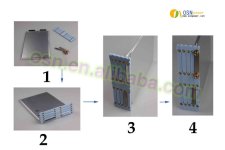
Then I proceeded with my MAC/Trek build, wanted new battery and reconsidered the whole approach once again. I'm back to using the A123 AMP20 cells, and the maker kit from OSNPower, which is mechanical - a metal strip and pair of bolts per tab. The amount of time invested in making a pack went way down. Time invested was the whole reason I explored use of conductive epoxy to begin with.
OSN-AMP20-Assemble-sm.jpg
 
Chalo said:
That resistance is probably mOhm per square cm of bond area, assuming the bond conforms to spec for thickness and surface prep. That's a very different thing than what you seem to be talking about.

The units for electrical resistivity for any material are in ohm-cm (or milliohm-cm or ohm-m or ohm-inches, etc). If you look at my link, you will see that the epoxies manufacturer uses these units, and the resistances are even lower than my example.

The reason the are ohm-cm is that when you multiply by thickness and divide by area, you end up with ohms. Units should always "cancel" out in an equation to only leave the desired units...otherwise something is wrong.
 
arkmundi said:
I experimented with a couple different brands of conductive epoxy with my A123 26650 battery build and could not make it work! The conductive properties of the epoxy were OK, but the bonding was atrocious.

I would guess that surface prep is very important, as is clamping during curing. Cleaning the metal first is probably very important, and maybe fine scuffing. And of course, some epoxies are very sensitive to mix ratios and mixing thoroughness. But, that said, I don't want to be the pioneer that uses $1000 of batteries in bonded battery pack that ends up with a bunch of detached cells after a few months of riding vibrations and temperature cycles. Repairing that would be near impossible. I wish someone had tried though ;)

As for soldering, it scares me. The batteries aren't made for it, and depending on chemistry and electrode construction, you may or may not get away with it. Who knows if you are significantly shortening the cycle life when done. I personally don't want to risk it.

I am buying parts for my own spot welder, but have yet to put it together and dial in the power. Have 2.4F of capacitors, some good SCRs, a foot switch,6ga welding cable & a 15V10A power supply. Just need an enclosure, some copper rods for electrodes, and a few misc items. Plan to try to weld thick (.005"-.010" nickel) in my pack. Want to get the welder sorted before I buy batteries.
 
Dougt said:
As for soldering, it scares me. The batteries aren't made for it, and depending on chemistry and electrode construction, you may or may not get away with it.
Well, yea, some caution is good. But I made it work and did not experience any noticeable damage to the electrical characteristics of my 12S8P set of A123 26650 cells. Its not the preferred approach.
I am buying parts for my own spot welder, but have yet to put it together and dial in the power. Have 2.4F of capacitors, some good SCRs, a foot switch,6ga welding cable & a 15V10A power supply. Just need an enclosure, some copper rods for electrodes, and a few misc items. Plan to try to weld thick (.005"-.010" nickel) in my pack. Want to get the welder sorted before I buy batteries.
I believe you're taking the better course and have a spot-welder of my own also in my wish-list of things. FYI, my AMP20 cells and maker-kit came from OSNPower. They offer a spot welding service. Possible to have a tab spot welded to every cell. Then its a matter of soldering or bolting the tabs together. I like my packs made in such a way as they can be de-constructed, so as to replace bad cells and extend the life of the pack as much as possible. There has been some forum discussion that the positional location of a cell in a pack is a factor. That cells at the two polar ends of a pack will see degradation fastest. So it makes sense to want to replace those cells when needed and getting longer service life from the remainder.
 
arkmundi said:
I believe you're taking the better course and have a spot-welder of my own also in my wish-list of things. FYI, my AMP20 cells and maker-kit came from OSNPower. They offer a spot welding service. Possible to have a tab spot welded to every cell. Then its a matter of soldering or bolting the tabs together. I like my packs made in such a way as they can be de-constructed, so as to replace bad cells and extend the life of the pack as much as possible. There has been some forum discussion that the positional location of a cell in a pack is a factor. That cells at the two polar ends of a pack will see degradation fastest. So it makes sense to want to replace those cells when needed and getting longer service life from the remainder.

Yes that is true; many places will do a free spot welding service if you buy the batteries from them. I haven't ruled that out yet, as their equipment and technique is more dialed in, but there are three major drawbacks: 1) I want a high amp (150a) pack, and many of these battery places only put 1 or maybe 2 spot-weld pairs per cell and use thin cheap, .05mm to .1, nickel plated steel strips that are only 5mm wide. 2) as you say, deconstruction is important if you don't want to trash the whole pack when one cell goes bad, that means the arrangement of the strips is important to diagnose and identify the bad cell and replace it without collateral damage. 3) if you need to do a repair, you need a spot welder anyway.

Why are the polar ends of a pack more likely to degrade fastest? I would think they would do better since they are usually at the physical ends of the pack and thus have better cooling. I don't see why, as the drain is the same regardless of position....unless the BMS isn't a great design and does a poor job of balancing/limiting the ends. Haven't gotten my head into the BMS design or sourcing yet.
 
Dougt said:
Why are the polar ends of a pack more likely to degrade fastest? I would think they would do better since they are usually at the physical ends of the pack and thus have better cooling. I don't see why, as the drain is the same regardless of position....unless the BMS isn't a great design and does a poor job of balancing/limiting the ends. Haven't gotten my head into the BMS design or sourcing yet.
It is just a general observation, confirmed by many forum members. I won't speculate as to why its the case, leaving that to those with the research capability to answer. The point is you can start out with new identical cells and towards the end of a pack's lifetime, some of those cells will likely fail sooner than others. So pack construction is a worthwhile consideration. A pack spot welded will be less amenable to deconstruction. If I were to make a pack from cylindrical cells (I'm sticking with the prismatics for now), I'd get my cells from OSNPower, have them spot-weld tabs to each cell, to my specification. Then on receipt, I'd use a bolt assembly method to connect them in them in series and parallel to yield my voltage and amp-hours.
 
I agree, bolting prismatics is way easier, but you have less options and usually a higher price for the same performance as cylindricals. And prismatics have less flexibility in form fitting your battery space. I am still looking at that option

As for cylindricals, specifically 18650 size, I've given spot welded pack construction a bit of thought recently. My application is probably going to use 12p20s. That is a lot of batteries. The problem is that with so many in parallel, it is more difficult to identify the bad cell. Identifying a bad bank in series is easy, as you can monitor the balance during charge or discharge. So my goal is to make it easy to detach the balance leads to further identify the specific bad cell in a bank.

Basically I plan to break it up into two 12p10s packs, and spot weld each pack as if they are 6 separate 2p10s packs, and then lightly spot weld strips to make the balance leads and complete it into a 12p10s pack. That way I can identify the bad series bank, rip off the balance strip, identify the the bad cell (well there will be two candidates since its 2p, but close enough), and cut the bad cell out, probably by carefully grinding each spot weld down or dremel cutting the strip. If the cells are safe enough chemistry, could even use a small bit to drill out the spot welds, destroying the bad cell but making a cleaner removal. Of course, the end banks will be slightly different, as the balancing lead has the full pack current going through it, so those nickel strips will likely be pre-solder (before spot welding to batteries) a heavy wire (12ga or so) to each of the 6 strips and then run those out to solder to the main pack lead, which will be 6 ga. Don't know if any of that makes sense...I might need to post a drawing.

Not to complicate things more, but in reality, the series running nickel strips will be half-width strips running in parallel, so that spot welding the second pair doesn't short the welding energy through the previous spot welds. Commercial spot welding strips often have slots in them achieve the same goal.
 
Back
Top