Cromotor + MethTek Monster 24FET + 20S lipo build

Thanks again for the great advice. I now have the confidence to start with this project. I will be shopping around and have some nice stuff delivered to me. No doubt I will run into problems. If I cannot find a good solution here on ES, I will post my question. So expect some nice questions coming up in a few weeks...

I plan to document my project as well. Not that I think most people here really need to know, but I started this thread, And might as well use it..
 
Hi all,

After a lot of reading, and a lot of PMs/emails with different people, I have made up my mind. But first I would like to thank Cellman from Emission-free.com and Reinhard from ElectricWheels.de. They have spend a lot of time and energy in answering my questions, and their advice has been invaluable. However, while getting to know their systems and with my own lack of EV knowledge slowly disappearing, I found myself looking for something more. I ended up with ordering from -methods. 'nough said. I can't thank him enough as well!

So the following has arrived or is on it's way to me. Essentially, I am rebuilding my bike completely...

  • Fox 32 TALAS RLC 140mm front suspension fork (already implemented)
  • Front and rear 203mm disc brakes with Avid Juicy 7 hydraulic brakes (front implemented, rear to follow after implementation of rear disc brake adapter / torque arms). I will convert them to E-brakes using Reed contacts and a magnet
  • HT3525 sensored hubmotor in a 26 inch rearwheel and 7 or 8 gear freewheel, tested by -methods
  • -method's 40A super controller (100V capabilities, 4110 fets, etc) (to be implemented, soldering the shunt, and control current from the CA)
  • half turn throttle, CA, PowerLED CREE lamp, and other goodies
  • 4x 37V 10S1P 4.5Ah bricks to create a 74V 20S2P 9Ah pack. And yes, I have the 10S 1010B charger as well.
  • 2x Mean Well 350W PSUs for bulk charging of 2x 10S2P packs. Will set HVC at 41.5V.
  • 2 meters of red and another 2 of black 10 AWG silikon wire and Nylon XT60 connectors (to allow at least 60A continuously if I have the guts)
  • external auto thermometer
Still in doubt about fast tyres, because I want to ride in winter as well, and then I will probably need some spikes... And I will just have to learn to be gentle with the throttle when going uphill because probably even the HT clyte can be burned... :evil:

In two weeks I should have everything in. Then I will go on a holiday (Italy), and after that the fun will start... building, yippie!!
 
Hi all,

I am reading a lot of very useful and interesting threads here. However, the info is all over the place, so I have decided to start editing my first post in order to keep track of all the info. Maybe it will be of use for other noobs like me.
 
Today, 2x 10S1P 4.5Ah bricks arrived, together with the iCharger 1010B+ and a 350W PSU, all from HobbyKing. Both bricks were perfectly balanced with all 20 cells between 3.84V and 3.85V. I am impressed. The bricks are heavy, the 1.25 kg or something is quite substantial.

So, apart from reading up on the ES forum, I have been thinking how to proceed with this build. The most important thing here is that I need to be able to bike every working day. Not only to get myself to work, but also to bring my kids to school. So I need a modular approach to building my bike, with small changes applied / implemented at a single time, and with preparations off-bike prior to implementation. This is my current plan, open for suggestions:

  1. Start with replacing the LiIon battery with a 10S2P 9Ah Lipo pack.
    • Preparations needed: solder all necessary connections, including combining the balancing connectors, install charger and PSU, charge the pack to 4.20V per cell, prepare bike for lipo installation without disturbing the current LiIon pack.
    • Implementation: replace the connection between controller and LiIon pack with a connection suitable for the Lipo packs, install the Lipo pack on the bike, and drive away. Estimated time that the bike can not be used = approximately 20 minutes.
  2. Replace front mechanical E-brake with hydraulic DIY E-brake (Juicy Seven). Preparation needed: testing of the new DIY Reed based E-brake. Estimated nonfunctional time when implementing + testing = 45 minutes
  3. Replace current motor + controller with HT3525 + -methods' controller + throttle + CA. Preparation needed: solder all necessary connections, testing. Estimated nonfunctional time when implementing + testing = 3-4 hours. This is obviously a weekend task.
  4. First test the new system with 10S4P 18Ah. Then see what happens when switching to 20S2P 9Ah. If needed, I can always choose to go 20S3P 13.5Ah.
  5. I save programming of the CA, programming of the controller, and soldering the shunt for later....
 
Lebowski said:
maybe with all this power it's better to replace the basic chinese bicycle for a more sturdy one :D

Ha, you are probably right. However, I already replaced the front suspension fork with the Fox 32 TALAS 140mm. That is a DownHill fork, so it should be able to take a hit. The frame is not so bad, aluminum with nice welds all around. The rear dropouts are flat, and there is already a torque arm available. I will receive another torque arm from -methods, so with two torque arms, and an additional rear 203 mm disc brake on top of an A2Z disc brake adapter, the frame should be able to survive the clyte. We will see.... :lol:

I looked at FS frames anyway, but at this moment I do not want to spend that money on a frame. Let's brake this cheap chinese E-bike (CCEB) first.

On another note, last night I was reminded again what a noob I am. I tried to create a parallel harnass for the two 10S bricks to create a 10S2P pack using 12 AWG wires. I spent more than 30 minutes trying to heat the wires with a standard iron, without luck. So I decided to google what I did wrong. Apart from being reminded of the usual stuff (clean tip, solder tip, start tinning individual ends), I also learned again that a large tip will transfer heat better than a small tip. And I had been trying to heat a 12 AWG wire with a microsolder tip with a diameter of 5mm. No wonder it did not work... :oops:

So I replaced the tip with a 1cm flat screwdriver like version, and it worked much better. Will try to get an even better one, though. Good solder helps a lot as well.

Anyway, I was not able to finish the job. I also do not like these HK 4 mm gold connectors. The soldering is fine, however the plastic cover is a pain in the @ss. I still have conducting parts sticking outside the connector, despite pulling and pushing like crazy to get the connector in the cover completely. So, I will wait until the Hextronik nylon XT60 connectors come in, because with 2x 37V I do not want to run any risks of short circuits. I see the whole exercise as a practice run for noobs.

I also have 10AWG wire coming in, to be prepared for the future. I can try not to repeat my mistakes. Probably will make other mistakes... :mrgreen:
XT60.jpg
 
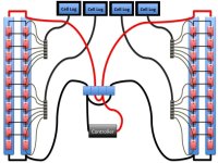
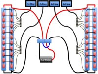
The 10S1P bricks come with 2x JST-XH 5S balance connectors. This means that for a 20S2P setup, I need at least 4 CellLogs to keep track of the voltage at 1S level, and each 1S level will have 2 cells in parallel. Ordered some JST-XH connectors and CellLogs, and I plan to build a semi-permanent 1S level voltage monitoring setup.

CellLog-8M.jpg

JSTMF-5S-20cm.jpg
 
Received the Cree powerled 12V lamps today. I had ordered 2 of them for USD 72 per piece, free international shipping. They look very slick and robust, with a metal casing and L-shaped base connector. I tried them with a fully charged 3S pack, and the light is crazy. I have no means to measure lumen, but the vendor claims 1600 lumen per lamp. I don't care, it is awesomely bright light. I will probably keep using the 3S pack (or an 8cell AAA equivalent) until I have settled on a battery voltage (10S or 20S) and then use the appropriate DC/DC converter. I may also just step down from 37V from one 10S pack anyway, even when using a 20S pack, using Lyen's DC/DC converter (or something equivalent).
4LED.jpg
 
Also, I am still thinking about a good wire schema. My main considerations are weight (max 4x 10S bricks), capacity, ease of use, and performance. I would prefer not to take more than 4 lipo. For long distances, that would mean connecting all 4 bricks in parallel, giving me a pack of 10S4P 18Ah. At 37V 40A, that is still 1480W, which is nice. However, if I would like some performance, giving up some capacity, but still carry no more than 4 lipos, I end up with 20S2P 9Ah. At 74V 40A, it is of course double the power, most noticeable in increased speed, increased acceleration, increased torque when going uphill, but a very much smaller mileage. I also need to take into account charging. Now, when having a 10S4P pack, I can easily connect it to my charger, and charge all 4 Lipos in one go, balanced and all. In the 20S2P configuration this is much more difficult.

Balanced charging would require that I just connect the correct balancing plugs in parallel. So that means a standardized connector that connects to either Cell Logs or to the balancer of my 10S 1010B iCharger, but only in 10S4P config.

Therefore, I am now exploring a way to easily switch between the two schemas below. The first for high capacity and easy charging. The second for high performance. I may just end up with gluing different configurations of XL60 connectors together, so that my charging setup is only possible in one way.. Slide1.jpgSlide2.jpg
 
I started just as obsessive like you with cellogs, bm6s, cellmeters etc, then I noticed that they are not really useful, even worse, they disballance your pack. Now all this meter stuff is garbing dust and I bulk charge and discharge my batteries, checking the top balance with MKS propo from time to time. I can go over 20 cycles with less then 0.04V balance difference(in 24s pack). If you permanently connect cellogs, prepare to balance charge the pack about daily or so (depending on capacity) :)

Edit: I also doubt you will notice some efficiency difference between 20s and 10s if you install 3 speed switch. What I mean is 20s 50% speed limit is about 10s 100% if you go easy on throttle when accelerating in first case.
 
parabellum said:
I started just as obsessive like you with cellogs, bm6s, cellmeters etc, then I noticed that they are not really useful, even worse, they disballance your pack. Now all this meter stuff is garbing dust and I bulk charge and discharge my batteries, checking the top balance with MKS propo from time to time. I can go over 20 cycles with less then 0.04V balance difference(in 24s pack). If you permanently connect cellogs, prepare to balance charge the pack about daily or so (depending on capacity) :)

Edit: I also doubt you will notice some efficiency difference between 20s and 10s if you install 3 speed switch. What I mean is 20s 50% speed limit is about 10s 100% if you go easy on throttle when accelerating in first case.

Hi Parabellum,

Thanks! I guess, it is just my own fear of lipo-issues that I need to overcome. I do see your point, but at this moment I am not comfortable around these high voltage (>24V) lipos without all the X-mas bells. However, it does seem reasonable to design the system so that I can easily connect and disconnect the CellLogs. That means that when I have the confidence to go without the CellLogs, I can do it.

With regards to the efficiency. Are you saying that going full throttle on 10S4P 18Ah would be of similar efficiency (aka mileage) as going easy on the throttle with 20S2P 9Ah? Because, if that is the case I will definitely rig the pack for 20S2P.
 
hjns said:
However, it does seem reasonable to design the system so that I can easily connect and disconnect the CellLogs.
Exactly, it is a way to go.
hjns said:
Are you saying that going full throttle on 10S4P 18Ah would be of similar efficiency (aka mileage) as going easy on the throttle with 20S2P 9Ah?
In performance, speed and efficiency 10S 20Ah controller limit, no throttle limit 100%= 20S 10Ah controller limit 50%throttle limit (If you ride this 2 settings, you will not be able to distinguish which is which, only difference regen braking will work down to lower speeds for lower voltage). Actually there will be 0-5% difference in efficiency, but it is kind of covered by lower wiring resistance loses in between battery and controller at 20S.
Only issue, 3 speed switch is limiting throttle not current, so it is up to you for efficient ride.
 
parabellum said:
Only issue, 3 speed switch is limiting throttle not current, so it is up to you for efficient ride.

Thanks again! I should be able to limit current in the CA as well on the fly by adding a potentiometer, right?
 
hjns said:
parabellum said:
Only issue, 3 speed switch is limiting throttle not current, so it is up to you for efficient ride.

Thanks again! I should be able to limit current in the CA as well on the fly by adding a potentiometer, right?

Donno, have no CA. :) But halving throttle and current should act as reconnecting to 10S, staying really on 20S
 
OK, I am rethinking the lipo pack setup.

Also, I found a very nice thread with people showing how they mounted the batteries on their bikes. Link added to the knowlegde base that I am creating in the first post of this thread.
 
Thinking about how to travel with my lipo. I took one of my side panniers, and tried to fit some lipos. It turns out I can actually carry the balanced charger and 350W PSU with 6 or more 10S bricks. Need to think about it more...

Anybody knows how I can change the resolution/size of the image links? Because the resize function in the BBCode does not seem to work, and I would hesitate to resize the original image.

Photo%2025.09.11%2006%2044%2012.jpg


Photo%2025.09.11%2006%2044%2042.jpg

Photo%2025.09.11%2006%2046%2012.jpg
 
Ok, so more goodies came in, and ordered some more as well. This is what was delivered by -methods:
  • -methods 36-72V 40A controller IRFB4110 mosfets
  • CA
  • half twist throttle
  • 8-gear freewheel
  • Clyte HT3525 in 26 wheel
  • Torque arm
Everything was packed in one big box, inside a lot of foam, and the individual parts were also well packed in bubble plastic.

Also, from HobbyKing, I now have 4 bricks of 10S1P. Carrying all 4 of them is about 5kg, which I find quite heavy. I will try with 2 of them first, and see how far I can get. So 20S1P 4.5Ah, here we come. The 3kW should give me some serious power, and I ordered a thermometer that will read up to 125 oC (275 oF). Ordered 3x DC/DC multivoltage converter (Lyen), one for the wife bike, one to drive my 2 CREE powerleds 1600 Lumen at 12V, and one for my HTC HD2 satnav (OziExplorer) + Iphone 4 at 5V (see manual by Lyen as well). The two DC/DC converters intended for my bike will each tap from a different 10S1P brick.

I made a 12AWG harnass for two bricks of 10S1P in series, to get a 20S1P 4.5Ah pack. Connected all electronics, except the motor. CA showed voltage of 75V, which corresponds nicely with my volt meter. I do not have a good test setup where I can test the motor, so I will need to build the wheel into the frame before actually trying. I will also need to create a parallel harnass for charging, and I will adjust the balance wires that I ordered previously from HK. It usually takes 3 weeks before my orders from HK turn up at my front door.

My iCharger 1010B charges a 10S with 9.9Ampere, so one 4.5h takes less than 30 minutes to charge. Therefore, 6 lipos in parallel will charge in 3 hours, which is perfectly acceptable for me. I am just wondering if there is any other reason (apart from time) to go for a bulk charger from Mean Well?

I am afraid that that will all have to wait until after my holiday, as I leave on Friday... :cry: Weather forecast for Italy is great, though, so being there with the family is priceless! :D
 
Hi all,

I am back. We had a great holiday.
2011-10-02%2018h42m38_.jpg

2 miles from Grosseto, Tuscany, Italy


2011-10-03%2017h43m18_.jpg


2011-10-04%2016h31m22_.jpg

2011-10-11%2012h45m52_.jpg

2011-10-11%2012h46m32_.jpg

2011-10-02%2017h16m21_.jpg

My 3 oldest

2011-10-02%2017h21m05_.jpg

And the youngest one (almost 2y/o)

2011-10-07%2019h37m03_.jpg

2011-10-07%2019h20m43_.jpg

2011-10-14%2018h44m47_.jpg

All photo's taken with a Canon EOS 1000D Tamron 28-300mm 3.5-6.3

After coming home and cleaning up, I started working on a parallel charging balancing harnass. I used some of the tips here on the forum to make a harnass that can charge 6 packs of 10S lipos with my balanced charger at 10Amp. That means, that when I come home after a day's work and start charging right away, they should be charged before I go to bed. Will post some pics tomorrow.
 
Photo%2015-10-11%2022%2015%2011.jpg

In the lower left there is a 10AWG wire connected to two 10AWG pieces. The upper right shows three 12AWG wires connected to one fo the 10AWG pieces.


Photo%2015-10-11%2022%2029%2056.jpg

Same as above, however now the other 3 12AWG wires are connected to the other 10AWG piece.

All soldering is done with a 100Watt iron, and in the pictures the copper wire is visible that makes the soldering much much easier. Of course, everything will be covered with shringtube in due time.
 
links to photos restored above
 
parabellum said:
So, you just tie short ends with cooper wire and then sock with solder?

Yes, pretty much.

What I do is the following:
  1. Let's take the example of 1x 10AWG + 3x 12AWG. I strip the insulation for about 10 mm from the ends of all the Wires. When soldering both ends, I therefore prefer to have wires of at least 40 mm long, so that in the middle I have at least 20 mm covered with insulation. As the solder tends to flow with the strands to inside the insulation, this gives me some leeway and keep some flexibility.
  2. I bind the insulated ends of the 12AWG wires together to prevent any slipping.
  3. I then tie the naked ends of the 10AWG and 12 AWG wires together.
  4. I put a little bit of solder to a clean tip and start heating the copper wire around the wires.
  5. I put the solder (with raisin nucleus) to the copper wire about 1 mm from where my iron touches the copper wires.
  6. As soon as my solder starts to flow, I move the solder away from the iron tip, while keeping the solder in contact with the copper wire. The solder will continue to flow, and the heat will continue to spread to the other parts of the copper wire and the encircled large wires, so that in the end the whole connection is so hot that I can see that the 10AWG and 12AWG wires are soaked with solder.
  7. Let cool. Put shrinkwrap around. Done

I will post some more pics in this post later today.
 
So, I screwed up (literally) and attached the freewheel to the Clyte without the proper washer, leading it to bind up. I am in contact with -methods for the appropriate freewheel extractor tool to correct things. He has send one to me free of charge (great service, -methods!!), and it is due to arrive in a couple of days. I will make some pics and post the results. Should not be difficult to solve though.

I now have two harnasses. One for 10S6P which will be used for parallel balanced charging of a maximum of 6 packs of 10S lipos and testing my bike at 37V. Wires are 12AWG. I also finished a harnass for a maximum of 20S3P 13.5Ah pack with 10AWG wires overall. The 72V should give some nice performance to my HT3525. For commuting, 2packs of 10S in series (20S1P 4.5Ah) will provide me with enough power and Ah and charge the lipos in the evening. For long trips during the weekend / holidays, any combination of 4 to 6 packs will provide me with a very nice range, especially in 10S6P 27Ah configuration. Below the harnass for 20S3P, which will be used for commuting in 20S1P config.
Photo%2023-10-11%2011%2050%2017.jpg


The temp sensor has come in, as did another 2 packs of 10S lipos from HK. In a lot of lipo orders from HK during the last 2 years, this is the first time that I received a pack with at least 1 and maybe 2 dead cells. The other pack is fine and well balanced at 3.84 or 3.85V for each cells. However, the pack with the dead cells shows 0.00V for one cell (might be broken balancing wires, because total voltage says 35V) and the other cell shows 1.51V (definitely a loser here). All 8 other cells are nicely balanced at 3.84 or 3.85V. I sent HK a mail and asked for a new Lipo. Let's see how they react.

In the meantime, I have opened controller to take a look. It seems to have 12 mosfets 4110 and 2 caps of 100V. I want to be able to draw minimally 65A and preferably 80-100A. All at 20S lipo (84V max, 72V nom).
Photo%2023-10-11%2010%2045%2031.jpg


I also seem to have found the famous shunt that people seem to fill with solder in order to decrease resistance and allow for higher currents. Can some people confirm this is the shunt?
Photo%2023-10-11%2010%2046%2023.jpg


Now I also noted that people mentioned that the soldered path on the backside of the pcb needs re-inforcement. Can somebody confirm which paths really need another 10AWG wire soldered onto it?
Photo%2023-10-11%2011%2023%2024.jpg


In order to get to 80-100A, should I do something else?

Thanks!
 
Back
Top