Cycle analyst v3 and greentime controller help

sketchism

100 W
Joined
Feb 17, 2016
Messages
177
Location
GC, Australia
Hey guys sorry to be a pita

Hooking up my ca to a greentime controller with ca plug and the ca comes on and reads the throttle response etc, but the controller doesn't react to it.

It feels like the controller isn't turned on even tho the ca is being powered by it, I can't find the on/off wires on the controller) are they now controlled by the ca? If so how can I get it to turn on?

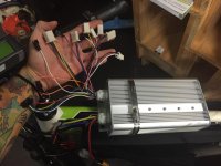
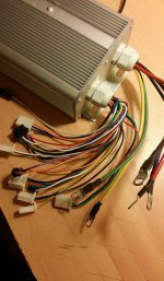
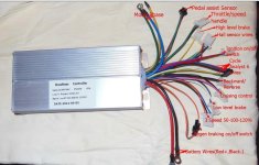
Attached a pic of the rats nest it anyone can point out the ignition wires if that's what I'm looking for.

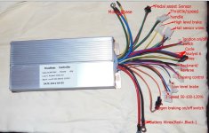
I can only find wiring diagrams for a different version which does have ignition wired as a red/black pair this controller doesn't have?
12825317_10204643700527443_1087643260_n.jpg
12782386_10204643698407390_1153138596_n.jpg
image.jpeg
image.jpeg
 
could this be the issue?
maybe the controller was set up for a v2 and i have a v3, although the date on the controller says build late 2015

https://endless-sphere.com/forums/viewtopic.php?f=4&t=37964&p=608858#p608858

has anyone experienced something similar?
 
The real question is: Where did you get that controller that provides no wiring diagram?

Observations:
  • A quick Google search turns up these pinouts which indicate that some model of Greentime uses a red/purple pair for ignition.
    http://www.pedelecs.co.uk/forum/threads/wanted-someone-in-england-to-wire-up-my-ca3.22854/
    https://endless-sphere.com/forums/viewtopic.php?f=30&t=40900&start=500#p707152


    • Code:
                      Resistance to   Resistance to
                      thick black     thick red       Function
      
      Thick wires
      Red             -               0               Battery +
      Yellow          9k24            -               Motor phase
      Green           9k24            -               Motor phase
      Blue            9k24            -               Motor phase
      Black           0               -               Battery - / Gnd
                                                     
      5 wire connector
      Red             -               -               5V hall sensor power
      Yellow          4k13            -               Hall sensor signal
      Green           4k13            -               Hall sensor signal
      Blue            4k13            -               Hall sensor signal
      Black           0               -               Gnd
                                                     
      3 wire connector
      Red             -               -               5V throttle power
      Green           10k             -               Throttle signal
      Black           0               -               Gnd
                                                     
      2 wire White/Bla
      White           -               -               low level brake
      Black           0               -               Gnd
                                                     
      2 wire Red/Purp
      Red             -               0               Key switch power (Battery +)
      Purple          22k             -               Key switch input   <==========
                                                     
      Single wires
      Purple          22k             -               ?
      Green           9k4             -               ?
      Yellow          24k             -               high level brake (regen?)
  • The ignition wire gets hooked to Vbatt so we expect the purple wire to be the ignition wire and the red wire to be tied internally to raw Vbatt.
  • Inspecting the photo you provided to a Greentime model different than yours shows a purple and red pair to a 2-pin connector, so that seems to correspond to the search post above.
  • You spaghetti photo has no red/purple pair but does have a loose purple wire - oddly with a ring terminal - which may match the power ring terminals in size. This makes me think this is the ignition wire, however, this post suggests it's just Vbatt for a battery indicator:
    • https://endless-sphere.com/forums/viewtopic.php?f=30&t=40900&start=900#p1117526
      John Bozi said:
      halls
      cycle anaylyst
      orange black blue = 3 way switch pretty sure
      red green black = probably throttle
      purple black = backwards
      white black = low level brake
      yellow alone = high level brake
      white white = can be connected self study
      orange orange = can be connected regen
      purple with circle ending to nowhere = battery indicator <=====
      pink black = cruising control
  • However - you have plugged in the CA and it is alive, which it should not be UNLESS the ignition wire is getting power - so that is confusing since you did not mention hooking the ring-terminal purple wire to anything. The red CA-DP connector wire should be tied internally to the ignition wire. So - maybe John Bozi is correct and the ring terminal pruple wire is just Vbatt.
  • In your spaghetti photo, the CA-DP connector has the blue and black wires interchanged at the connector. This is not necessarily a Bad Thing since they can go to the same place on the shunt internal to the controller - but it doesn't inspire confidence.
Thoughts:
  • Don't hook up the CA until the bike works properly without it, otherwise you have no idea where the problem lies - and right now this looks like a controller wiring issue, not a CA issue. Wire the throttle directly to the controller, etc. and get the bike working first.
  • Power up the controller.
  • Measure from the purple ring to battery Gnd with a DMM.
    • If it's Vbatt, then John is correct and it's a battery indicator just hooked internally to Vbatt that bring out that voltage.
    • If it's 0, then it's not - (maybe ignition wire) ???
  • Measure the voltage across the red/black wires of the throttle connector.
    • If it's 5V, then the controller is alive and you either have no ignition wire, or it's there and hooked up by default (?).
      The throttle should work and the bike run, etc. If not, it's some other wiring or controller issue (because the CA is not hooked up...)
    • If it's 0V, then
      • Your ignition wire is not hooked up. Depending on the test above, my bet is on the ring-terminal purple wire, but since hooking Vbatt to just about any non-ignition controller wire will fry the controller, you probably need to get some documentation or open the controller and trace the wire instead of rolling the dice.
      • In this case your ignition wire is not hooked up but the CA was running (Vbatt on the red CA-DP wire). This seems to indicate that the CA-DP connector is wired incorrectly so the ignition wire does not turn off both the CA and the controller as per normal. After you get the controller running, you can add a switch to the red CA-DP wire or rewire the red CA-DP wire to the controller ignition wire either internally or externally.
  • After the controller is running - then hook up and install the V3 according to the Guide.
 
Thanks very much for the comprehensive reply that's why I love this place!

so the purple was definately ignition, the ring terminal was a bit confusing and i was hesitant to just go putting 90v on random wires but that solved that problem and it's powered on now.

The ca throttle didn't work with it yet so I connected The throttle directly to controller which made it respond to input, albeit run backwards and smash me in the shins but we're getting somewhere lol

So I tried re routing the ca throttle output to the controllers normal input to bypass the resistor which solved that problem too,

CA now controller the controller & it gave me full throttle response from the ca, in reverse, I've really got to remember that lol now to fix it running backwards,

Update: shorting the rev wires makes it run fwd but not sure that's the best solution haha
 
Good news!
So it looks like the purple ring terminal is the ignition wire but the CA=DP connector is wired directly to Vbatt instead of the ignition wire as in other cases.

I might recommend:
  • Cut the existing red wire controller connection to the CA-DP connector pin in the middle. Run the controller side of the red wire (Vbatt) to your keyswitch and the keyswitch to the newly cut red CA-DP connector wire and to your purple ignition wire. This will have the keyswitch turn the whole bike on/off.
  • Wire a handlebar kill switch in the purple ignition wire so that it will switch off the controller but leave the CA running.
 
Thanks very much I'll do that :)
Yeah the ca turning on even tho ignition wasn't connected was throwing me off a bit

I'm trying phase combos at the moment I can get it to run perfectly backward but only barely and noisily and with a lot of phase wire heat forwards, still trying combos
 
got it! thanks a million for the advice, i couldn't resist taking it for a spin (its 4:30 a here)

big difference from 13s to 24, now to put it together neatly and hide that controller haha
12782384_10204645329168158_1318158314_n.jpg
 
Glad it worked out.
Because moving the green CA-DP throttle wire resolved the throttle issue, I suspect the controller CA-DP connector was wired using a diode for the older style CA V2 interface.

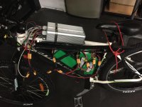
Looking at the bike pic, I might suggest turning the controller around so the wires exit in the rear. As it is now, you will be driving rain directly into the cable seals. They may hold and not leak, but it looks to be a suboptimal arrangement. (The devil is in the details.)

Anyhow, thanks for getting back with your results. Hopefully, another builder or two will benefit....
 
not a problem :)

oh haha the controller wont stay there i just needed somewhere to mount it while i worked out the nest of wires, i will probably mount it wire side down under the battery box under an alloy splashguard like i have done on a different bike which worked well.

while i've got you here, i bought the CA-DPS version because thats all the local shop had in stock, but i dont need to use the sensor, i cant seem to find where to set it to pull the speed from the halls rather than the magnet speed sensor, i tried setting the poles from 1 to 23 or so but i cant get a reading from anything other than the magnet?

is this software editable or can i unsolder/swap speedo wires?
 
sketchism said:
...i dont need to use the sensor, i cant seem to find where to set it to pull the speed from the halls rather than the magnet speed sensor,...
is this software editable or can i unsolder/swap speedo wires?
Please see "Appendix B. Add/Remove Wheel Speed Pickup Sensor" of the [strike]Un[/strike]official Guide.
Then reset the poles appropriately according to section "6.14 Determining Pole Count".
 
thanks very much, its what i was thinking i would have to do but better than winging it and guessing haha
 
Back
Top