Cycle Analyst V3 preview and first beta release

marcn said:
We're using an Aux Pot, and would like to have it control the PAS level when we're using AutoTorqPAS. Is this possible, and if so how would it work in relation to the tables found on page 52 and 53 of the guide?

For example, at <=55RPM we would like 500w, and upto 90RPM, 1000w.

Can we use the 5k potentiometer to adjust these values on the fly from 0,0 to 500,1000w, once we've set the max limits (by inputting trqscale, asstfactr and asststart)?

Edit: Just read that the potentiometer input would only change the AsstFactr, and using AutoTorqPAS would have no effect. Is this correct?
You are sort of mixing up operating modes - I know - it's confusing...

  • If you put the pot on AuxPot and configure it for PAS, then it can be used to adjust the assist level 0-100%. When you pedal you get the fixed assist assist power set by the pot.
  • AutoTorqPAS is unrelated and is a hack that gives RPM-scaled assist by from a simple PAS wheel. The PAS wheel supplies the RPM information and a fixed voltage from the CA supplies a fixed phoney 'rider pedal torque' signal. This allows us to configure the CA for a torque BB and use the RPM scaling that comes with that kind of device - even though there is no real torque sensing. So - you use the table to make the settings (in your case for 500W/1000W you use the 500W/x2.0 cell). It works like the first case above except the faster you pedal the more assist you get.
  • There is another variation that uses a pot with AutoTorqPAS where you INSTEAD wire the pot according to "6.6 PAS Assist Control without AUX Pot – DIY Virtual Torque Sensor". In this case the pot supplies a variable instead of fixed 'phoney rider pedal torque'. You adjust the 'assist' level NOT by using AuxPot, but rather by adjusting the phoney 'rider torque' pot on the PAS 'TRQ' input. This is not basic AutoTorqPAS - it's a variation...

    In this 'variation' scheme AuxPot is not involved in any way and you can use it for a three speed switch (Max Current Limiter, preset switcher, or whatever) as you choose. For example it might be configured as a three speed switch limiting Current so the switch would control the max current using the throttle and the pot would control the assist power from PAS. In either case you can flick the switch or turn the pot on the fly.

I use AutoTorqPAS with the 'virtual torque sensor pot' setup on my bike. As I adjust the PAS-pot upwards I can see the power go up on the main screen. I can also flip the 3-position switch and the new AuxPot throttle current limit briefly displays on the screen. So I might be pedaling along on PAS with the throttle current turned down for bike path level power and see a hill coming up. I can downshift to increase my cadence to get more power, or turn up the pot to get more assist, or just flick up the 3 position switch to turn up my available throttle power so I can just goose it over the rise without messing with the assist and gears....

In any case, I recommend that you arrange the pot so it can be manipulated easily to tweak the assist setting - preferably without releasing the grip (at least keep it toward the grip and away from the stem). This is particularly handy if you are trying to match speed with another rider. For example, Here's a post on using a modified thumb throttle for aux pot input or see my build thread for a bar-end pot mount, or I think Kepler has thumb pot setup on one of his bikes - lots of options...
 
Thanks for the response teklektik!

Just so I can make sure I'm on the right track.

I'm using a 12 pole cadence sensor and an Aux Pot from here http://www.ebikes.ca/shop/ebike-parts/ca-accessories/aux-input/ca3-auxp.html, that I want to use to adjust the PAS level using AutoTorqPAS (TorqPAS), since rpm-proportional assist would be nicer than AutoPAS.

From what I've read, the AuxPot will control the AsstFactr in PAS mode when TorqPAS is enabled.

IF I were to set TrqScale, AsstStart, AsstFact to 36.4, 252, 3, which yields 500W upto 55RPM and 1300W upto 90RPM, would adjusting the AuxPot only yield an AsstFactr of 1 (min), 2, or 3 (max), or would it be linear from 0-3, OR am I completely off track here?

Edit: Just had a light bulb moment and understood what you're referring too with the pot variation. If I was to use the typical Aux Pot, presumably the adjustments made to AsstFactr via the Aux Pot are not linear, and behave more like a 'switch' between assistance levels and thats why the variation method exists (as well as those who wish to use a 3-way switch as well)? [strike]E.g. using the Auxpot would only yield the below E.g using 43.7, 303, 3

AsstFactr 3 = 500w @ 55RPM, 1300w @ 90RPM
AsstFactr 2 = 400w @ 55RPM, 1040W @ 90RPM
AsstFactr 1 = 200W @ 55PM, 520W @90RPM

Whereas using the variation, the values aren't so much fixed but linear, dependent on the range of the pot.[/strike]

Just read one of your previous posts that states Aux Pot will adjust AsstFactr from 0-100%
 
marcn said:
IF I were to set TrqScale, AsstStart, AsstFact to 36.4, 252, 3, which yields 500W upto 55RPM and 1300W upto 90RPM, would adjusting the AuxPot only yield an AsstFactr of 1 (min), 2, or 3 (max), or would it be linear from 0-3, ...
You are on track. If you use a pot connected to AuxPot you will get continuously adjustable assist 0-3. If you connect a switch to AuxPot, you will get distinct levels of assist according to the discrete voltages of the switch setup. AuxPot can be connected to a pot, a switch, a throttle - anything that gives a variable voltage. You pick the particular device according to what AuxPot controls and the kind of physical control you want... typically a pot for continuous PAS adjustment and a switch for quick-change power levels. Read the Guide section on AuxPot again - whatever it's controlling gets scaled according to the AuxPot input voltage - pots are continuously variable, switches are discrete - AuxPot doesn't know or care what it's hooked up to....

marcn said:
Edit: Just had a light bulb moment and understood what you're referring too with the pot variation. .....
No - not correct at all.

AuxPot can only be configured in any given preset (there are three max) to perform ONE control function - if you have a pot on it and use it to control PAS then you must, for instance, configure a fixed max current for throttle control because AuxPot cannot be used to adjust that as well. But - you might in another preset disable PAS and configure the AuxPot input to control maximum current - again it has just one control function but it's different in the second preset. In this example your pot would control PAS in the first preset and max current in the second. The 'variation' technique allows you to have TWO control devices -- an adjustment (pot) for PAS (using the TRQ input) AND use AuxPot for some other purpose like limiting current (perhaps a switch but maybe another pot!) - both in the same preset.

It may be best to just ignore the variation concept since it's a bit of a hack and requires custom wiring anyway. Just stick to the simpler AutoTorqPAS solution using AuxPot.
 
Would it be possible to run a CAv3 with both the screen and buttons removed.

For a minimal stealth build, removing the main PCB from the case will make a good space saving.
 
NeilP said:
Would it be possible to run a CAv3 with both the screen and buttons removed.
Justin will need to weigh in on this - but here's a semi-informed opinion until he can (a non-authoritative answer is probably pretty worthless, but here goes):
  • Removing the buttons presents no issue at all.
  • The LCD unit has two parts: the display interface and the LED backlight.
    • I believe the interface is 'push only with dead wait loops' and no status is actually read from the unit, so disconnecting the LCD shouldn't upset the main PCB - which should continue to think it is displaying normally - even though no one is really listening.
    • The main PCB power regulation relies on the LED backlight. You would need to jumper the backlight pins with a suitable resistor or zener to get PCB power - pretty simple.
So - looks promising. As always, if this is pressing an email to Grin is the best bet.

EDIT - Hmmm - although you can configure it without the buttons, zeroing the torque offset or zeroing the shunt current would be a little problematic.
 
NeilP said:
Would it be possible to run a CAv3 with both the screen and buttons removed.

For a minimal stealth build, removing the main PCB from the case will make a good space saving.
What would be the intended benefit of using the CA-board over a programmable controller (and save even the space of the PCB)?
 
I don't know of a programable controller that can take THUN inputs, throttle mapping etc, for the price of a basic XieChang style controller. Some of these new ones may have all tha abilities like a CAv3 but not in the same price bracket.
 
teklektik said:
EDIT - Hmmm - although you can configure it without the buttons, zeroing the torque offset or zeroing the shunt current would be a little problematic.

Umm true. So i guess do the build and initial calibration etc with display and buttons on, maybe a jumper cable. Then remove once setup

I am thinking for end user, non configurable 'stealth' UK road legal setup that user cant tinker with, with torque PAS with potential for off road setting activated by RFID or mag wafer switch.

So no display, just single power on/off switch, for non techy rider. Pack with BMS

THINKING more, maybe make a 'disgnostic' tool, consisting of the disp, backloght and buttons, for setvicing, logging etc.
 
teklektik said:
NeilP said:
Would it be possible to run a CAv3 with both the screen and buttons removed.
Justin will need to weigh in on this - but here's a semi-informed opinion until he can (a non-authoritative answer is probably pretty worthless, but here goes):
[*]The main PCB power regulation relies on the LED backlight. You would need to jumper the backlight pins with a suitable resistor or zener to get PCB power - pretty simple.[/list][/list]
So - looks promising. As always, if this is pressing an email to Grin is the best bet.

Teklektik is as usual quite correct here. The CA will run just fine without the LCD attached but you would need to short out the two leftmost pins of the LCD header, under the text "-LED+" in order for the device to power up. You can keep the LCD module handy and press the header pins into the holes and hold it at an angle to make good contact if you do occasionally need the screen to change things in setup etc.


There are also some miniature 16x2 character LCD modules that could also achieve the same stealth effect without sacrificing a screen. You'd have to do a header adapter but something like this is only a little over 2" x 1", so about the same footpring as the CA PCB
https://www.crystalfontz.com/product/cfah1602syyhet-character-display-module-16x2

We wind up with more than a few CA3's with slight defects on the LCD module like missing pixel rows etc. which we put on our garage shelf. So if anyone is after a unit for hacking off the screen just send an email to ebikes.ca to see what's there.
 
NeilP said:
Thanks for the info

that is great to know

ditto that...
 
izeman said:
Alan B said:
I think it only calculates it under certain conditions, so it won't change until the conditions trigger a calculation. It needs the right data to do the calc.
maybe justin could add some comment here. he would be the only one to explain the algorithm w/o guessing :)

Sorry to have missed this discussion earlier. The algorithm indeed only works to update RBatt when there has been a noticeable change in the current draw, and then the extent to which RBatt is affected will be proportional to this change in current. So if the min delta A is set to 1.0 Amps, then any changes in current less than this will be considered too low to result in a detectable change in the voltage and a reliable value. When the changing current is just a bit higher, say 2.0A from one point in time to the time 1 second previously, then a new RBatt is calculated from
Code:
RBatt = V2 - V1 / A1 - A2
However, the display won't update to show this value, instead it will slightly adjust the existing value towards this newly calculated value in a rolling average. So if the previous value was 120 mOhm, and the value just calculated was 140 mOhm, it might (with just a 2A difference in current) update to 122 mOhm. If the difference in amperage was a lot higher, say you gun the throttle and draw 20 amps all of a sudden, then the CA will have a lot more confidence in the newly computed value of RBatt since there will be a correspondingly much higher voltage drop. In that case if it calculated 140 mOhm, the display might update all the way from 120 to 130 mOhm. Just a few more twists of the throttle and it will be at 140 mOhm.

The protected settings that Teklektik showed allow you to tweak this behavior a bit:
RBatt Filter Rate If you increase this value, then the display will converge faster to the newly computed RBatt value. But it also means that the RBatt will bounce around and change more during the course of a ride.
Min Delta Amps for RBatt This is the threshold discussed previously. If you have a really low resistance battery ( < 100 mOhm), then it would be prudent to increase this to whatever value gives at least a 0.2 to 0.3V drop from the pack. So like a 50mOhm pack needs about 5A to produce a meaningfully measurable voltage drop for the CA to do a resistance calculation.

The objective of the RBatt indicator is to somewhat track the internal resistance of the pack over the course of the ride, since it can vary a bit both with state of charge levels and also definitely with temperature. If you plug in a fresh pack and want to see it's internal resistance, you need to first throttle lots of amps and release several times in a row until you see it converge to the same value.
 
justin_le said:
Min Delta Amps for RBatt This is the threshold discussed previously. If you have a really low resistance battery ( < 100 mOhm), then it would be prudent to increase this to whatever value gives at least a 0.2 to 0.3V drop from the pack. So like a 50mOhm pack needs about 5A to produce a meaningfully measurable voltage drop for the CA to do a resistance calculation.


Is that in the UUG Tek? I feel that woudl be worth including if not. Pretty sure my large Nano Tech packs are pretty low in IR. Not somethign i remember seeing in the guide
 
NeilP said:
Is that in the UUG Tek? I feel that woudl be worth including if not.
Nope. There are at least a couple things in play here:
  • The 'hidden' Setup parameters are somewhat technical to explain and are hidden for a reason. In general mucking with many of these has deleterious consequences - although arguably this is one of the more harmless. I have left discussion of these to Grin and Grin Technical Support so that revealing or recommending alterations would be their responsibility along with the likely increase in Support time to 'fix' resulting custom-generated problems. Even in my post above I was intentionally vague - although I could have provided more technical detail, doing so was quite outside my purview.

  • The UUG also contains no instructions whatsoever on using the CA Setup program - a whole different product that deserves it's own instructions. To tie the Setup program into the UUG would mean that the UUG would become out of date whenever the Setup utility changed. This means talking about menu options, etc is off-limits. Hidden parameters present a problem in that they cannot be set by the CA proper - the subject of the UUG.
That said, since Justin is publishing the info here and the settings cannot materially affect operation of the CA, a section might be added that skirts detailed definition and HowTo of operating the Setup program. I am agreeing with you, but also trying to adhere to very clear decisions about what should and should not appear in the UUG (well, from my perspective).
 
Well everyone, as you all know Teklektik has done a phenomenal job of creating the most comprehensive "unofficial" user manual ever and helping out countless people in troubleshooting and setting up their CA3 devices here on ES. He's done all that selflessly on his own initiative without any explicit compensation from us, just as an avid end-user who understands the device inside and out. And I have been both eternally grateful and also somewhat guilt-ridden for having such a talented guy contribute freely to this product's success.

Anyways, some time ago he suggested (seeing how I was seriously time deprived and project management impaired) that he has the skills and time available to be involved in the actual firmware development if I was up for that. It's taken a while to sort out the details of that arrangement but I think at this point we're comfortable proceeding with Teklektik actually on the team. As a senior software guy with much more experience in complex projects like this than me, and with an avid interest in seeing ongoing CA3 improvements, this should bode very well for the pace and regularity of CA3 development updates. Which under just my own command have had some very long lapses. So I would like to publicly say to Tek, huge thank you, and huge welcome, and I think all CA3 users should be relieved to see a dedicated developer on board.

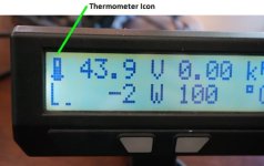
On that front, the Prelim10 build of CA3 firmware should be made available here in a matter of days. From an end user's side not a whole lot will have changed. There are a few tweaks, like the behavior if you have a speedo sensor and magnet pickup is much more resilient against double-bounce glitches in the sensor, so those occasional bursts of 200+ mph readings should be a thing of the past. As well, an update courtesy of Teklektik, if you exceed the threshold temperature and are in thermal rollback then the battery SOC icon will periodically update with a flashing thermometer symbol, (with the height of the mercury in the thermometer scaled to your ThreshTemp and MaxTemp values):
ThermometerIcon.jpg

However, it's the changes behind the scenes in the structure and organization of the codebase which are huge, since this is the first release done in a collaborative manner between myself and Teklektik and that required a massive rework to bring things inline with standard coding practices more suited to team development. There's a chance that in this restructuring we may have introduced new bugs so we want to get it out there in beta testers hands soon before making the official 3.00 build.
 
justin_le said:
So I would like to publicly say to Tek, huge thank you, and huge welcome, and I think all CA3 users should be relieved to see a dedicated developer on board.

Wow, that's awesome news! I think the future of the Cycle Analyst & it's support is bright :D
 
Thanks J. I think the thing we all look forward to is more time in your quarter to develop new cool stuff like the Satiator, web tools, and - well it's a long list! The Grin team has delivered terrific products and support - it's great to be part of it. :D
 
teklektik said:
Thanks J. I think the thing we all look forward to is more time in your quarter to develop new cool stuff like the Satiator, web tools, and - well it's a long list! The Grin team has delivered terrific products and support - it's great to be part of it. :D
i'd like to say a big thank you to you as well! there can be noone better found which such in-depth knowledge of the CA.
 
That’s good news to hear Teklektik!

I am having a problem with my CAv3 that I got 2 years ago. Recently I had the boot up issue where only the backlight came on. The next week after a trip to California when I turned on my bike the backlight did not even come on for the CA. I searched around and found out about the boot loader but the program can’t find my CA.

Things I have tried:

Before the California trip:
First tried on 100v >> just the backlight came on
Tried 125v >> just the backlight came on
Tried 75v >> just the backlight came on

After the California trip:
Turn on my bike at 100v with my CA v3 >> nothing comes on (no backlight or letters/numbers)
Plug my CA into my dad’s bike >> nothing comes on. (His is 48v)
Plug my dad’s CA v2 into my bike >> Seems to work normally.
Try using throttle on my dad’s bike with my CA plugged in >> very low power is allowed (probably the low voltage I set for the throttle on my bike) When the CA is unplugged I get full power on my dad’s bike. >> Seems like the CA is doing something?
Measured voltage out of the output power jack on the CA >> full battery voltage (normal)

Ran boot fix >> The program timed out because it can’t find the device.
Ran Perlim6_NoEprom >> The program timed out because it can’t find the device.
Ran Perlim6_NoCal >> The program timed out because it can’t find the device.

I haven’t used my CA for two months or so but it was working great back then. If anyone has any ideas for me to try please let me know.
 
Just yesterday, out on a ride, about 3-4 mile in, I get some weird throttle cut-off.
Under power accelerating then cuts out.
Speedo is reading ZERO.
I can hear the 'tick' as the wheel magnet crosses the speedo sensor.
Pulled all the connectors apart and put them back together...thinking a bad plug connection. nope.
Has been working fine for over a year.
Today out to try again.
I notice a 490mph readout on the CA3.
Then I notice a capital 'S' on the flag screen.
At first I was getting a speed reading if I held the front wheel off the ground and spun the wheel, then when I started rolling...nothing.
Now nothing at all. Off ground or rolling.

Is this next firmware update related to this?...just have to wait?
Can we do a system reset to clear this odd behavior?
...Or am I having some other problem someone knows about?

Thanks
 
Paladin said:
I notice a 490mph readout on the CA3.
Then I notice a capital 'S' on the flag screen.
At first I was getting a speed reading if I held the front wheel off the ground and spun the wheel, then when I started rolling...nothing.
...
Is this next firmware update related to this?...just have to wait?
...
Or am I having some other problem someone knows about?
Ya - you probably have a wonky speedo pickup. This is a known but rare issue and the fix is to first try realigning the pickup and magnet as described in the manual. Failing that, you should contact Grin for a replacement pickup.

What is happening is that contact bounce or some weirdness of the magnet passing the reed switch is causing spurious short duration pulses that the CA interprets as super high rpm - typically in the 400-600mph range. This immediately sends the CA into speed limiting (the cap 'S' you saw) and cuts the throttle.

The p10 release out in few days (it's being tested now) specifically addresses this issue. The new firmware filtering should fix you up but otherwise you will need to pursue a replacement pickup.

To get riding you can temporarily re-position the pickup away from the magnet which will make the bike go but obviously without speed/distance information. :(

EDIT -
Paladin said:
At first I was getting a speed reading if I held the front wheel off the ground and spun the wheel, then when I started rolling...nothing.
Now nothing at all. Off ground or rolling.
Hmmm - this is a little odd. Not sure I understand this completely. Do you mean the CA gets the 'S' and stops immediately, or just there is no speed reading? I'm wondering if you have a broken wire in your pickup cable that was intermittent and finally broke completely. Try going to the Setup SPDOMETER section preview screen and watch the little arrow as you diddle the spoke magnet back and forth in front of the pickup. It should point up and down as the magnet passes. If not, you've lost your pickup connection.
 
Scott said:
Ran boot fix >> The program timed out because it can’t find the device.
Ran Perlim6_NoEprom >> The program timed out because it can’t find the device.
Ran Perlim6_NoCal >> The program timed out because it can’t find the device.
This does sound like the boot issue. I haven't tried the boot fix myself, but there are reports of rare cases like yours where the CA won't wake up enough for comms to work. There's a chance this might be another known issue with comms timing. There are work-arounds for that with the regular updater, but not for the boot fixer.

Try the procedure Justin outlines in this post.

If this fails, shoot an email to ebikes.ca Support for more specific assistance or replacement.
 
Thanks for the fast response, teklektik.
Realigned it and added another magnet...no go.
The only thing that I have change lately is a Magura throttle.
The original connection on the CA3 for the throttle had the +5v(red) wire connected to the Potentiometer(not the throttle) on the CA3 circuit board.
I connected the Magura to the Throttle +5v on the CA3 board.
That's the only thing I have changed in the last month or so.
May have got a stick into the pick-up...and I did add the speedo pick-up, will check my solder.
Thought I would relay that, in case it had any bearing on the matter.

thanks again!!
 
Back
Top