Cycle Analyst V3 preview and first beta release

eTrailster said:
I cut all my connections and rewired the bike. Everything else seems correct, but the regen problem popped up from nowhere. The CA wire colors matched the colors from my Lyen controller.
...
The only other difference I can find is at rest I reed zero Watts. It used to read 5W.
Could I have reversed the S+ and Sp connections?
The 0W symptom would seem to indicate that your shunt is not hooked up correctly. However, although it's possible that you have S+ and S- reversed (white and blue wires respectively), almost anything is possible since you have rewired the bike.

At this point, trying to ascertain the wiring error by examining symptoms is not a certain path to success and swapping 'suspect' wires that have unknown connections seems ill-advised.

You need to get a meter and verify the continuity and routing of your connections from the controller CA-DP connector to the CA PCB.
 
teklektik said:
eTrailster said:
I

The 0W symptom would seem to indicate that your shunt is not hooked up correctly. However, although it's possible that you have S+ and S- reversed (white and blue wires respectively), almost anything is possible since you have rewired the bike.

At this point, trying to ascertain the wiring error by examining symptoms is not a certain path to success and swapping 'suspect' wires that have unknown connections seems ill-advised.

You need to get a meter and verify the continuity and routing of your connections from the controller CA-DP connector to the CA PCB.

Hey teklektic, thanks for your response. I was hoping you would find this. Magical thinking drove me to try switching S+ S- = regen%999, 25W no load, -8.5Ah. I'm continuous beyond the CA-controller connection, but didn't check at the CA PCB. That segment was untouched. Beyond potential S reversal, routing is simple enough. Although I was hoping for a software related fix, I fear your first inclination must be correct. It must be the shunt. What do I do?

I really don't want to open up my controller to replace/re-solder the shunt. I don't suppose an external shunt can be used without removing the existing one? More magical thinking I suppose.

Then again, I may be on the wrong track. Just to make certain - riding the bike like this temporarily won't damage anything, right? I'll simply get the erroneous data?

Thanks.
 
hello
I try to add a diode (b-e junction of a si transistor) as temperature sensor on CAV3 p10
connected to CA, with 0 degre, I read 0.76V; with 100° I read 0.63v
so If I understand correctly, I have a degre/v of 100/(0.63-0.76) => -0.769V
if I enter 0.76 in 0 deg and 0.769 in T scale, the temperature value displayed is ok in absolute value but negative (-)
where am I wrong ?
 
So I'm hooking up the temperature sensor that came pre installed on my leaf motor 1500w. I asked for a 10k NTC so hopefully this is not the issue.

The sensor appears to use the hall sensor for a ground as I can only see the signal wire come out of the motor.
By default the cycle analyst displays 4.99v for the temp sensor as it pulls up to 5v. When I connect the signal wire it immediate drops to something like 0.1-0.2v with a -36 reading. It's at least +25c here. I tried connecting to the other wire at ca side but this has no effect on the 4.99v ca reading.


Can anyone help?
 
mchlpeel said:
So I'm hooking up the temperature sensor that came pre installed on my leaf motor 1500w. I asked for a 10k NTC so hopefully this is not the issue.
...
When I connect the signal wire it immediate drops to something like 0.1-0.2v with a -36 reading. It's at least +25c here.
It seems that it's not a 10K NTC thermistor.

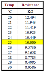
Check the resistance between the thermistor signal lead and Gnd and you should see 10K at 25degC (hence the name). Yours seems to have an effective resistance of about 0.25K at room temperature - so not what the CA needs. Here's a few nearby resistances for a 10K part:

RvsT_TableExcerpt.png
Beyond needing a 10K NTC part, it should have a beta of 3900 as described in the Guide "5.7 Temperature Sensor". Also, a temp rating of 150degC is a good bet to keep the readings fairly accurate at elevated temperatures.

The hard part about temp sensing is getting the wire routed into the motor. You have the wire - so the fix is straightforward. Open the motor, snip the leads on the bogus part (just leave it glued in place), solder in the new part (it's non-polarized so any which-way will work), and epoxy it in the valley between two phase coils or to the stator tucked under a phase coil. JB Weld is a readily available high temp epoxy.
 
With regard to the thermistor

Would it not be possible to add a calibration screen for the temp sensor.
Using two easy to replicate 'standard set points, Ice and steam/boiling water, so zero and 100 degrees could be set
 
NeilP said:
With regard to the thermistor

Would it not be possible to add a calibration screen for the temp sensor.
Using two easy to replicate 'standard set points, Ice and steam/boiling water, so zero and 100 degrees could be set
how would you use that? the thermistor is fixed inside the motor. you can't put the whole motor in boiling water :)
and if you buy a thermistor you just have to buy the correct one. measure resistance at room temperature and if you get 10k it's ok.
 
Would be easy enough (for me at least) to direct a jet of steam over the thermistor if it was in place in the motor...or pack with ice for zero degrees.
But I was more thinking about calibration of a 'in theory correct (via it spec) thermistor

I bought a load of them , all 10k and 3900 from RS components..not some cheap e-bay random spec stuff but from an proper supplier, and I am convinced the temp they are giving is out by 8-10 degrees high.

I walk in to my shed , with a current ambient temp of about 18 degrees, and even as I power the bike on, the temp is reading 25 degrees within the controller...where it has been powered off all night.

So to be able to correct this via a calibration screen would be ideal.
 
hello
I try to add a diode (b-e junction of a si transistor) as temperature sensor on CAV3 p10
connected to CA, with 0 degre, I read 0.76V; with 100° I read 0.63v
so If I understand correctly, I have a degre/v of 100/(0.63-0.76) => -0.769V
if I enter 0.76 in 0 deg and 0.769 in T scale, the temperature value displayed is ok in absolute value but negative (-)
where am I wrong ?

no idea ?

I want to use a linear temperature sensor (diode) but with negative coefficient !
is it possible ?
how ?
 
jc.maquet said:
no idea ?

I want to use a linear temperature sensor (diode) but with negative coefficient !
From "5.7 Temperature Sensor" of the Unofficial Guide:
Supported Devices: This input can be supplied by either a 10K NTC (negative temperature coefficient) thermistor or a PTC (positive temperature coefficient) linear temperature sensing element
The present implementation does not support other NTC devices.
 
Thanks teklektik

Is it a chance that new release will support linear NTC in future ?
or
do I have to replace my calibrated sensor from my motor
in this case, which sensor is the best ?
 
jc.maquet said:
Is it a chance that new release will support linear NTC in future ?
Justin is away just now, but I had already put this on the list to discuss with him early next week to see if he wishes to include the feature - and if so, will we target 3.0 or 3.1.
Will advise.
 
no advantage, but it more easy to find, just took it from an old board
I didn't find ntc 10k 3950 on here ebay
 
teklektik said:
jc.maquet said:
Is it a chance that new release will support linear NTC in future ?
...to include the feature - and if so, will we target 3.0 or 3.1.
Will advise.
Configuration of negative deg/V scaling coefficients (Temp->TScale) for linear type sensors will be supported in the next release (3.0p11) - to be released in the near future.
 
super teklektik !

by izeman » Wed Sep 02, 2015 3:02 pm

jc.maquet wrote:
no advantage, but it more easy to find, just took it from an old board
I didn't find ntc 10k 3950 on here ebay

those work fine: http://www.ebay.de/itm/10-x-10K-OHM-NTC ... 4163c7d837

this is a B Constant 4050K
I read max 4000K earlyer in this post ?!
 
Quick question...I hope
I am trying current throttle on 4.5kW peak and its smoothed out all my low speed low wattage ride soooooo much!!

Problem: I am getting some stutter as it climbs from 40-50kph on hard accel. I have limits on my amps and my watts...

Question: Should I be adjusting my gain up or down?? Or take one of the limits off??
 
r3volved said:
I am getting some stutter as it climbs from 40-50kph on hard accel.
Should I be adjusting my gain up or down?? Or take one of the limits off??
The power limit is actually derived from the current anyway, so I would recommend that you remove the power limit and rely on the current limit alone. If the 'stuttering' is due to the CA and not some other BMS or controller issue, then there are two strong possibilities:

  • AGain needs to be lowered to prevent overshoot and 'hunting' as the CA tries to keep things in check.
  • More likely since this is occurring on hard acceleration is that you are running into a speed limiting issue. I would recommend that you first try solution #2 below.

    From the Guide Section "4.9.2 Speed Gain (PSGain, IntSGain, DSGain":
    The V3 Unofficial User Guide said:
    Because the speed PID controller tries to anticipate limiting situations before they occur, some vehicles may experience cutouts during hard acceleration. The problem arises as the vehicle rapidly accelerates toward the speed limit and the Cycle Analyst preemptively reduces the throttle to avoid overshoot – even though the limit has not yet been reached. This cutout symptom indicates that the DSGain setting is too high (too much 'future sense'). The CA cannot actually discern that meaningful limiting is in effect and so the associated 'S' limit flag gives no indication.

    The PID controller employed for speed limiting is of a type that classically presents a greater adjustment challenge.
    If speed-related surging or power cutouts occur, apply one of these two remedies:
    1. If Speed Throttle or enforcement of SLim->MaxSpeed are desired, please follow the tuning procedure for the speed controller outlined in 'Appendix D. Tuning Speed Control Gain Parameters'.
    2. If Speed Throttle and maximum speed limit enforcement are not required, disable the speed control logic:
      set SLim->MaxSpeed to the maximum value, IntSGain = 100, PSGain = 0, DSGain = 0.
 
r3volved said:
I still don't really know what 'gain' is
Ya - I need to fiddle the Guide to present that in a clear way.

Basically, the CA has a bunch of software 'controllers' that look at different inputs like current, speed, etc and compare them to configured target values. In the case of Current Throttle, the target value is the computed current from the throttle setting and the actual value is the shunt current. The difference between the actual and target values represent the 'error' in behavior. A controller takes this error and uses it to 'correct' the throttle signal to the motor controller. The various Gain settings are the multipliers (like a volume control) that determine the amplitude of the 'correction'. High gain means a small error has a whopping big impact; small gain means things must go further awry (bigger error) before much 'correction' happens. The CA basically sits in a loop, doing these error->correction calculations endlessly.

So - with a high gain, it's often the case that the correction is so huge that it overshoots the target, the CA over-corrects, and a surging pattern of ongoing overcorrection arises (throttle too high, oops, throttle too low, oops,...). With low gain, the CA pussy-foots and response is so slow that response is sluggish. The speed, terrain, and power-to-weight ratio of the bike all determine how effective a given Gain setting will be which is why you need to tune these parameters for your particular bike.

This is a vague hand-waving overview - the Guide "Appendix D. Tuning Speed Control Gain Parameters" has a better treatment of three different gain parameters and how they affect the CA's reaction to past, present, and projected future errors. This Wikipedia article also may give you added insight into PID controller operation.
 
Removing all speed and watt gains/limits worked well!!

So what I have is a single Amp limit set to 40a and AGain as 25. There is still a very slight stutter at near max rpm which may be some imbalance in the rpm range and not due to the limits...

Should the amp limit and the amp gain values have any specific direct relationship to one-another? Like should limit be directly divisible by gain or 2x more or anything specific?
 
r3volved said:
Removing all speed and watt gains/limits worked well!!
Excellent news!

To clarify why this worked (even though you had a super high speed limit that you never reached):
  • DSGain controls how much the CA pays attention to projected speed limit errors. When set too high, the CA gets scared that you will exceed the limit even though you haven't done so already (driving in the car with your white-knuckled mom who is berating you for speeding when you are really not speeding, just doing jack-rabbit getaways - she is reacting to the acceleration not the speed). By setting DSGain to zero, the CA loses its future vision and stops worrying about what might happen (leave Mom at home and mash the pedal).
r3volved said:
Should the amp limit and the amp gain values have any specific direct relationship to one-another? Like should limit be directly divisible by gain or 2x more or anything specific?
This is a good question, but sadly the answer is 'No'. If it were the case, we could automate it and setup would be much easier. Rats.
 
Ah many thanks!! That pulls me through the gain confusion...I thought it was an over-limit rollback thing - where hitting limit-x rolls back y-units...i thought that was the cause of my stutter - continuous limit-rollback-limit-rollback.

Am i correct in thinking that 'ignore' on limits is 999 (all 9's) and 'ignore' on gains is 000 (all 0's)?? Ignores the limit because it can never even approach it, and ignores the gains because it's essentially x0??

Setting limit to 0 literally limits it to 0, correct? I use position 1 of my 3pos switch as a kill with everything limited to 0 so no one accidentally actuates the throttle - it works, but is that a good idea/bad idea/irrelevant?
 
r3volved said:
Am i correct in thinking that 'ignore' on limits is 999 (all 9's) and 'ignore' on gains is 000 (all 0's)?? Ignores the limit because it can never even approach it, and ignores the gains because it's essentially x0??
Spot on.

r3volved said:
Setting limit to 0 literally limits it to 0, correct?
Yep. Also, a Gain multiplier of 0 gives 0 result so there is never any correction. We leave the Speed IntGain non-zero so the bike will actually get some throttle, but set other Gains so associated error correction is disabled.

r3volved said:
I use position 1 of my 3pos switch as a kill with everything limited to 0 so no one accidentally actuates the throttle - it works, but is that a good idea/bad idea/irrelevant?
This can work but is going after the problem indirectly, basically by messing up the way the CA responds to current/speed/etc errors. Instead of adjusting the parameters of its operation, just shut off the throttle entirely. You might instead: in preset 1, set ThrI->CntrlMode = Off(0V). This locks down the throttle voltage to 0V regardless of any other settings or operator action ("It's dead, Jim.")

If you wish, you can also set PrSt->PowerOn = Preset#1 which will make the bike wake up with no throttle. You use 'Hot Swap' to change to mode preset #2 with two button presses w/o going into Setup. Not truly secure, but at least it makes 'jump on and ride away' thefts less likely to succeed... (This setting can quickly get annoying, but it may have utility in some environments.)
 
Back
Top