Dyno Glide - Bixby - Cruiser Cafe Racer Builds

That's a nice looking tap guide. Did you make it? For what its worth, I am a full time machinist for a living and I stress over every part as well. I think that's just the nature of working with dangerous stuff and high tolerances. You are spot on about the confidence thing. There is a poster on the wall of our shop that says The harder you try, the luckier you get.

Do you know what type of connector the motor wires are terminated for? It looks like a metri-pack or weather-pack like the ones used on cars but Im not sure. I was considering using that connector on mine if I could figure out what it is. Looks like good crimps with water tight bushings on them.
 
recumpence said:
I love it! Good to see people learning as they go. That is the best way to learn new skills IMO. :D Matt
Thanks Matt!

DanGT86 said:
That's a nice looking tap guide. Did you make it? ... There is a poster on the wall of our shop that says The harder you try, the luckier you get.
Do you know what type of connector the motor wires are terminated for? It looks like a metri-pack or weather-pack like the ones used on cars but Im not sure...
Thanks Dan!
I made the tap guide in one of my machine shop classes at the local CC. Very useful - I use it all the time.

The connectors are "packard" type:
https://www.google.com/search?q=pac...o&sqi=2&ved=0CEQQsAQ&biw=1276&bih=650&dpr=0.9

Here is more info regarding the wires:
Phases:
Black = A , Green = B, Yellow = C

Halls:
Black = - or ground, Red = +5v, Green = phase A, White = Phase B, Yellow = Phase C, Blue is for Temperature signal.

Edit:
I found this:
http://www.whiteproducts.com/connectors.shtml
on this ES thread on water proofing connectors:
http://endless-sphere.com/forums/viewtopic.php?f=3&t=57202#p853526
 
very cool build! i love the frame and motor. great machining as well :D

if you haven't chosen a controller yet, i would recommend a greentime. i recently purchased a 24 fet 4410 that i run at 5kw. $125 or so shipped to my house. however i am running it with a hs3540, im not sure how well they would run with your Transmagnetics.

hopefully youre up and running soon, im looking forward to seeing it! i love all the mid drive builds popping up, definitely going to be my next build
 
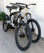
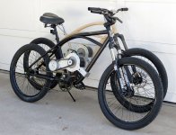
I mentioned that this was a 2 bike build and finally I have both coming along nicely.
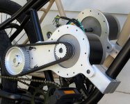
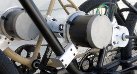
Completed the motor mounts for the Bixby, Dyno needs just a bit more work to round off the motor mount clamps. the Bixby frame has a slightly larger triangle, just large enough to require a deviation from the Dyno for the down tube clamp. Also completed was the key way broaching of the timing pulleys, thanks to my friend Don, who provided the press needed to drive the broach through the pulleys. Note the timing belt mounted on the pulleys for fitting. The pulley on the Transmag 532 motor needs to be completed and the belt also needs to be cut down from 30mm wide to 20mm for this application.
Dyno+Bixby3.jpgView attachment 1Dyno+Bixby7.jpgView attachment 6Dyno+Bixby2.jpgDyno+Bixby4.jpgView attachment 2
 
Oh Man,

Way too cool. These things have a "Big Block" look to them.

The motors and drive units look like they were part of the OEM design of the frames.

Very clean looking and the belt has that Harley look.

The only concern I have it the belt walking off the pulley. A simple flange on the motor pulley would be good. :D

Matt
 
recumpence said:
Oh Man, Way too cool.
These things have a "Big Block" look to them.
The motors and drive units look like they were part of the OEM design of the frames. Very clean looking and the belt has that Harley look.
The only concern I have it the belt walking off the pulley. A simple flange on the motor pulley would be good. :D Matt
Hey Matt, THANKS!
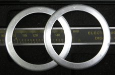
Guess I should have included this pic and the statement that the driving pulley is not complete. I still have to machine some of the depth and then machine a step for the flanges. I carefully machined the flanges off the pulleys to reuse them.
I wanted to have a peak and check what it looks like with the belt on, and did this before I completed the pulley. Pulley-Flanges.jpg
 
I spied this build via Google while trying to come up with some ideas on my Dyno electric build. Awesome build, looking great.

Here's what I'm working with. Want to add a double crown fork and use either a drum brake or disk up front. Motor? Not sure lol. It's sporting some Renthals off a 450 for bars at this point.


Anyways, great build!!!

Dan L.
 
Looking good. Everything looks really solid. I bet you could jam twice the power through that setup with no worries. I like the brake caliper bracket. What keeps it from rotating? What does it look like behind the dropout? Is the left chain line clearing the tire or do you still need some moving around of things?
 
Thanks spinningmagnets and EVTodd!

DanGT86 said:
Looking good. Everything looks really solid. I bet you could jam twice the power through that setup with no worries. I like the brake caliper bracket. What keeps it from rotating? What does it look like behind the dropout? Is the left chain line clearing the tire or do you still need some moving around of things?
The brake caliper bracket has a boss that fits into the dropout slot, and that is what keeps the bracket from rotating.
I got the bracket here: http://www.choppersus.com/ But they never have stock...and I had to machine down the boss because it was thicker than the dropout...and file the dropouts a bit to make room for the boss.

I got another one from here: http://custommotoredbicycles.com/ The websites a mess...you just have to poke around to find what you want...have not installed this one yet - so I don't know how well it works, but it looks like they have solved the too thick boss issue.

I dished the rear rim/tire to the right a bit and the chain line is just fine.
 
G'day RWP, fantastic builds. Truly inspiring.
Have you thought about making some panniers for the batteries? It worked for me on my mid drive cruiser.
 
love your work. I will keep watching 8)
 
Hey thanks guys!

Rider, while I like the look of the panniers on your project - well done! - it's not what I am aiming for. I plan to put the batteries in a fiberglass 'fairing' type thing that will fill the triangle below the cantilever frame elements and cover the primary drive pulleys.

I just got some Nissan Leaf battery modules and will do some surgery to get 16v-30Ah out of each 8v-60Ah module. The final battery will be 3 - 16v-30Ah modules = 48v-30Ah. It will weigh about 24 pounds and be about 9x12x4 inches in size.
 
Any progress on this build? I just busted my Transmag motor's magnets and I remembered you were the only other person I have seen building with them. I'm really curious how these motors perform so I figured I'd check in.

If you end up needing spare parts I have a now useless motor minus magnets as well as a fancy anodized black rear cover that is 1/2" shorter than the original.
 
DanGT86 said:
Any progress on this build? I just busted my Transmag motor's magnets and I remembered you were the only other person I have seen building with them. I'm really curious how these motors perform so I figured I'd check in.

If you end up needing spare parts I have a now useless motor minus magnets as well as a fancy anodized black rear cover that is 1/2" shorter than the original.

Thanks for checking in. I have not done a thing in more than a year. But I do hope to finish them - if only to get some $$$ ot of them.

How did you shorten the end plate and why? How are you cooling the motor with out the standard end plate? What do you want for the end plant only and for the motor including the end plate?

Cheers!
 
Sorry to hear they aren't up and running yet. I know how that goes.

I shortened the motor to fit between my cranks. I made the new rear cover 5/8" shorter with lots of open air space like an RC motor. This also required shortening the shaft by 5/8" to agree with the new bearing location as well as turning a new snap ring grove on the shaft. I also had the cover anodized because it was free at the time to do so.

The output side of the motor is unchanged other than a bolt circle of 10-32 mounting screws and the fan is still there. I took the gamble that the fancy spiral casting on the original rear cover was not essential to the airflow or cooling.

What ended up breaking the magnets was a stupid bit of impatience when I was disassembling the motor to install a temp sensor. Because of the fan, the shaft only comes out one way. It needs to be extracted from the drive end. The bearing was pressed into my rear cover such that I couldn't pull the shaft out easily. Instead of making a puller I tapped on it with a rubber mallet not realizing the rotor and magnets were bound on the stator laminations due to the magnetism. I thought the resistance I was feeling was the bearing fit when actually it was already free of the cover. I bet it was fine before that last mallet tap. Magnets don't like impacts at all. Oops.

So here I am faced with the decision to buy another motor and redo the shaft modifications just to salvage my custom machined cover or just give up on this motor. Transmagnetics said the parts would cost about as much as a new motor. They don't have just magnets laying around or I'd be fine. If I had the knowledge to rewind the motor or try to get more copper in it then I would probably get another one. That would be neat to have 2 stators, one to ride and one to experiment with windings, but I have been wanting to tinker with an RC motor build for years so this is probably a sign to just give up on this setup. I also have some shaft adapters to adapt the shaft to 3/4" for off the shelf 219 sprockets.

Not really sure how to price this stuff. Its hard to separate the value of a pile of parts from the machine and measuring time I have in them. How about $60 for the whole motor with the custom rear cover and the metric to 3/4" shaft adapter?

Either way, good luck with your builds. I can't wait to see one of these run somewhere other than my workbench.

1192hxl.jpg

54zmnn.jpg

deqt8h.jpg

15pqqeg.jpg
 
My first post in quite a while - I have been distracted. The city planning sucks in the city where I live, and as I have some background - I am being a citizen trouble maker - along with some others. It can be gratifying if slow work. If you are interested here is my project: http://www.OxnardCPG.com - https://www.youtube.com/watch?v=1w3TLJ8y0Oc

But to the point!
After all my work - I think I have given up on the transmags...I am getting older - tired of pissing against the wind...
I am going to put a 3Kw Cyclone of one of the bikes and see how that works out. With that Luna Cyclone and a 72V pack - it should kick ass.

The cruisers (Dyno Glide - Felt Bixby) both have that 68mm wide "American" bottom bracket shell. I got these adapters [http://www.bicycledesigner.com/bike-parts/heavy-duty-bottom-bracket---black.html] to replace the Ashtabula one piece cranks with the 3 piece more standard ones.

The question is whether the 3Kw Cyclone will fit on my project bikes with this bottom bracket adapter setup? Anyone have any experience with this setup and the Cyclone?

[moderator edit to fix link]
 
Sad to hear you are giving up on the motors. I can totally identify with your desire to cyclone it and just go ride. Highly custom work always spirals out of control into a big deal and tons of hours.

Is either bike to the point where you could test ride? I would love to hear some more feedback on the capabilities of the transmags. I debated "re-buying" mine to get a new rotor and magnets but ended up going with an 80100 instead. Having half of the motor sitting on the shelf keeps me wondering if it would be worth getting another. It just seems to risky since there is virtually no feedback from others on it.

If you truly give up on them, would the motors be for sale?
 
Back
Top