E+ powered by A123 20 Ah pack UPDATE

I don't understand
you replace just 2 cells in your old EMS battery B ?
I thought you ordered those 2 cells just to try soldering.
Are you not ordering another 8 cells to replace all 10 cells?
 
No, I re-measured and the LiMn cells would not fit (too thick) so I just ordered all 10 OEM LiPoly cells. They had copper tabs and were not too difficult to solder. Sometimes, I had the help of a third hand from my wife. The assembled battery works fine now.

The dead cell in the old battery was definitely identified by the bikes' controller and it prevented me from operating on it.
 
Something interesting I have noticed about the Battery B balancing circuit. It doesn't just progressively drain the highest Voltage cells to equalize with the lower Voltage cells. I observed the lowest Voltage cell at the start of balancing actually rises to a higher cell voltage than any other cell in the pack. As much as 150 mV at times. So the system is somehow using overall pack Voltage to boost the low cell Voltage to charge it up or some DC-to-DC conversion is going on.
 
BVH,
I don't know what kind of balancing Electric Motion Systems BMS LiPolimer uses.
If it used active balancing, meaning capacitor- based or inductor - based active balancing we should see 10 inductors one for each cell, or 10 caps one for each cell.
Or is it single capacitor active balancing?
Without close up picture of the BMS board it is hard to say.
BVH
Just make sure you report here your first ride on new cells.
 
kauaikit,
EPLUS cannot be powered on EMS Lithium Polymer only.
Front NMH hub communication cable at the minimum must be connected to the rest of system for Eplus to power up on battery B / LiPolymer/ .
Normally front power and communication are connected , right? , but only front comm cable
is necessary to power on battery B.
There is all sequence to power Eplus on EMS battery B.
It is discussed here page or two back.
 
Miro...Thanks.

Again, it's a shame the E+ front NiMH hub isn't a simple jumper fix like the original TF.

I haven't tried pulling the power off the battery board, to try a reboot, yet. I'll then decide the next course of action if that doesn't work.

The plan when I purchased this like new E+ was to get access to the frame, and the E+ setup was a bonus. I can always install the goodies from an extra original TF IO cruiser to this frame. :)

Though I understand the E+ is a 3 phase motor, and maybe the internal controller in the hub can be replaced with an external one and then use any battery source by bypassing the front hub and dash/controller?

Or, any ideas on how to bypass the heavy and outdated front NiMH hub battery on a E+?

Kit
S.CA USA
 
kauaikit,
thank you for answer
Can you spare me reading back posts and threads and tell me your story - when did you buy your Eplus, new?, used? what happened, what broke down?, what is not working now?
Sorry I helped more than one Eplus owner, cant remember.
I also deleted old Yahoo posts, cannot go reread them.
 
Miro, I remember back a ways in this thread, you mentioned something to the effect that there is a "counter" in the logic that must see a certain matching ratio of "counts in" (charging counts) and "counts out" (discharging counts) otherwise an error is set. Did you ever figure out if there was an "absolute maximum" number of counts that could not be exceeded either for charge or discharge? Or might it be the case that as long as counts in and count out somewhat match, there is no maximum number is the logic?

My B battery continues to work fine after the rebuild with identical replacement cells. My "A" battery still gives me 20+ miles of range with my style of riding.
 
Hi BVH,
I don't understand what you mean by "logic".
I was only experimenting with NMH front hub BMS electronics.
For sure SOC indicator displays bars based on Columb count of charge going into battery during charging and I AM not sure but I think main processor/PIC type/ on BMS stores new NMH charge info which is compared with actual charge registered. Based on this bars are displayed.
Of course when NMH cells age, it will accept less charge, less charge is registered , less bars is displayed.
Eplus would never generate error when less charge goes into NMH battery.
 
I hooked a 5 Ah lithium pack in parallel with my "B" battery right at the battery terminals. Prior, I equalized their Voltage to within 20 mV of 3.7 Volts per cell. I proceeded to charge the larger "pack until the factor charger completed the charge. I thought I might observe some type of error when the controller "counter" system counted too high from the extra Ah but I saw nothing unusual. When I turned on the display controller and switched to Battery "B", I was able to apply throttle normally for about 5 seconds and then the system shut down completely. I've tried every reset procedure I can think of but am not able to get the "B" battery to charge or discharge. If I remove the "B" battery from the system, I can use the Nimh pack normally. But if the "B" battery is hooked in the circuit, I can't even use the Nimh pack. The display just hunts back and forth between the "A" and the "B" and then errors out. Does anyone have any suggestions for any type of a master reset procedure to clear the "counts"? The controller is communicating with both the "A" and "B" batteries but something in the "B" system is locking out any use of both batteries.
 
So you connected parallel extra lithium battery to get more capacity?
yOU made it not absolute clear, but after hooking up your redone /replaced cells/ B pack , did it work normally with rest of EPLUS?
 
Yes, after the rebuild, everything worked fine. Both batteries worked with the controller as normal. Yes, I decided that I wanted more range, so I discharged the E+ battery "B" to 3.7 Volts per cell and did the same with the 5 Ah pack. Then I hooked in the 5 ah pack to the same terminals on the PC board that the E+ battery hooks to. I then charged the new larger pack. All charging indications were normal. The fuel gauge bars on the display increased as they normally do and the local multi-color LED on the battery itself, progressed in colors as it normally does. When the charge terminated, the charger LED turned green and the fan shut down as normal. I then turned the display on and checked that I had Battery "A" operation, which I did and then I switched to battery "B" and tried the same. The motor wound up as normal for about 5 seconds and then system shut down. Now, as long as the "B" battery is in the circuit, the display stays lit up - I cannot shut it off and the controller hunts from battery "A" to battery "B" about 5-7 times and then goes to err2 and stays there.
 
"on PC board",
you mean BMS board of battery B Lithium Polymer which pictures you posted in this thread? terminals using ALLEN screws? which ones?
Electrically you should not damage electronics unless you increased voltage too much on that terminal.
Did you checked voltage on that terminal before powering your EPLUS?
What happened most likely you reset main chip/processor on board not correctly while connecting, reset failed.
Can you read any markings on that square chip/
It looks to me it is also PIC 18 chip. same as NMH board. But I cannot say from your pics.
 
miro13car said:
"on PC board",
you mean BMS board of battery B Lithium Polymer which pictures you posted in this thread? terminals using ALLEN screws? which ones? - Yes, the same two + and - terminals where the Battery "B" cables land.
Electrically you should not damage electronics unless you increased voltage too much on that terminal.
Did you checked voltage on that terminal before powering your EPLUS? - Yes, 41.95, or 4.195 Volts per cell so well within maximum spec.
What happened most likely you reset main chip/processor on board not correctly while connecting, reset failed. - I have connected and disconnected the battery from the processor board probably more than 50 times with no issues. Not sure why this time would be different.
Can you read any markings on that square chip/ - yes, pic and markings data below pic
It looks to me it is also PIC 18 chip. same as NMH board. But I cannot say from your pics.


Markings on the chip:

Microchip
PIC24HJ
128GP506
-1/pt
090504E
 
BVH,
I will try to help you as much as I can but I know only so much.
From my experience with NMH BMS,
I had unsuccessful connects also.
What I found out that "bouncing" connecting can confuse PIC chip - reset will not happen.
So put ring connector firmly against terminal DO NOT BOUNCE.
 
Time for a new bike for me. I'm looking at the Prodeco tech Oasis V3.5. I'll buy two batteries which will just about double my current range up to about 75-80 miles with my style of riding. Nothing proprietary about the controls system so I can experiment around. A new $65 controller will get me from the stock 20 MPH limit to 28 MPH and give me up to 1200 Watts of peak power, more towards what I had with the E+.
 
I understand your EPLUS works normally with NMH , right?
It as you said display/controller hunts between batt A and batt B, because it most probably lost communication with batt B electronics, are you sure RS485 communication cable, connectors are OK?
What error it display?
Do not give up so easly!!!
Don't even try to compare EPLUS with Prodecho
EDIT:
Error 2 is indeed lost communication. Now it all make sense.
 
miro13car said:
I understand your EPLUS works normally with NMH , right? Yes, works completely normal with Battery "B" comm cable disconnected.
It as you said display/controller hunts between batt A and batt B, because it most probably lost communication with batt B electronics, are you sure RS485 communication cable, connectors are OK? I assume communication is good because if the display is "off" and the Battery "B" comm cable is disconnected - The moment I connect the Battery "B" comm cable, the display turns on and begins its' hunt, then goes into error. If there was a connection "open" then I would not think the display would come on? So I think the cable connection is good but something in the programming has been damaged so the communication is not taking place over good cables.
What error it display?
Do not give up so easly!!!
Don't even try to compare EPLUS with Prodecho I'm very interested to know and enjoy opinions of others. I don't use the E+ cruise control, I don't use regen. My riding style is to always keep a slight "burn" in my legs while traveling between 12 and 18 MPH for distances of between 25 and 45 miles. If the Prodeco can achieve the same level of available power (1200 Watts) and can travel up to 28 MPH and provide the "upright" seating position that my back needs, then I will have all the performance criteria I have now and in addition, an additional 20 miles of range. Other than not having front suspension (which I can remedy) what will I be missing?
EDIT:
Error 2 is indeed lost communication. Now it all make sense.

In the end, I'm just ready for something new. I've had this bike since 2008 or 2009. Maybe I can sell it here and recover some funds.
 
there are five wires in comm cable,
I can imagine, if only one wire is broken, cold solder, pinched wire - display/controller cannot estabilish comm handshake with LiPolymer BMS.
The only way to make sure is to check continuity of EVERY wire in comm cable from disply/controller all the way to comm connector on LiPolymer BMS board.
You would miss riding experience , durability of motor , 85Nm of torque /!!!/ , smoothness, complete silence but if you just want to ride from A and B ....you know what I mean, devil is in the details.
 
OK you talked me into one last try. I have continuity on 5 of the 6 comm wires from the actual Battery B controller board header up to the display connector. There is no continuity on the Blue #6 wire. I wiggled ever inch of the cable vigorously with the cont tester hooked up but not a single peep. There are absolutely no signs of cable damage. Before I go pulling out cables from inside the frame, can you verify that you indeed have continuity from the #6 conductor in your "future Battery B comm connector" zip tied on the seat tube extension to the #6 conductor female receptor on the display connector? That cable run is not one continuous run. There are splices in the middle of the frame down tube. I can pull them out that far without having to lose the connectors inside the frame.

EDIT add: The "splice" in the frame tube looks exactly like the "splice" on the cable set that goes from the displays' other cable over to the throttle and incorporates the brake lever cable. It looks more like shrink tube put over a connector to keep it together permanently.

EDIT 2 add: I had an old throttle loom I changed out years ago with the same shrink tube as described above. I took it apart and sure enough, each of 6 small wires are solder-spliced. Some wires are spliced color-to-color and go back into the same loom, but 3 dont. They change colors and the loom they are in so there's a good chance that the blue wire may not show continuity because it goes somewhere else. Just guessing until I hear back from you.

Opps, Just re-read your above post and see that you say there are only 5 wires in the cable. At the Battery B controller board, the header contains 6 wires. The sixth wire runs out to at least connector. So are only 5 used?
 
in comm cable there are 5 wires plus the shield.
No blue wire.
So continuity on white, black, orange, red and green, plus shield, that is all.
Looks like you shorted something while connecting your extra 5Ah battery, it was bad idea to paraller 2 batteries of different capacity.
All worked after you rebuilt and connected battB.
Prodecho needs 48V battery to "come close to 28mph??? Really?
Must be really primitive basic controller not even sinusoidal PWM.

So here you are - what the difference USA design means. Why to carry 48V brick on this thing?
 
There was no short. There are 6 wires in my comm cable from the Battery "B" comm cable. The 6th blue wire in that comm cable is actually soldered onto the Battery "B" controller board. There is nothing electrically "wrong" with mixing same Voltage, different capacity batteries in a paralleled pack. Each different sized pack will contribute its' proportionate share of the load and the different sized packs will maintain the same Voltage down through discharge and through re-charge. That fact that the display controller power up completely normal and that the motor ran fine for about 5 seconds after my first connection indicates to me, that a programmed safety limitation feature was initiated and that it shut down the system - not that there was a short or paralleled pack issue. If those were the case, the system would not have powered up and the motor would not have run at all. In my opinion "USA" design is a weak point, not a strong point. It provides no flexibility for the owner/user to improve his or her system.

There's lots of advantages to a 48 volt system over a 36 Volt system. Less Amps for the same amount of work means smaller, lighter wires and motor components can be used. Less heat is produced. All other factors remaining the same, more torque is produced by higher Voltage. The Prodeco doesn't "need" 48 Volts to achieve 28 MPH. It is a factor of the programmed governed speed. There system will provide up to 1200 watts to the motor under 28 MPH so there is actually more torque, quicker acceleration and more overall power available for better performance. Why does Tesla and all the other electric vehicle makers use systems with Voltages in the multiple hundreds in their cars? Why don't they use 36 Volt systems? I will always prefer a system that can be tweaked by the user over a proprietary system.
 
BVH,
I would not argue here on Prodecho , edrive which needs 48V for what other just needs only 36V tells everything.
Drive like Eplus when not tempered with will work for thousands and thousands of miles, because it is designed to Western standards /electronics, protections, etc/ built with quality materials down to high quality steel.
In contrast Prodecho is assembled with off the shelf cheap China brand parts.
So comparing two is like day and night .
BUT this thread is about EPLUS , lets keep it that way.
So your Eplus worked normally with batt B after you replaced that cells in that battery, I understand, right?
I never said connecting 5AH battery caused that problem.
So I maybe didn't read your posts carefully,
are you sure motor turns for 5 seconds? , what battery symbol is displayed during that 5 seconds?
So it is not comm error to me. No way motor would turn when there is not successful "handshake" of display/controller with every component which has comm port.
BVH,
since your EPLUS works normally with NMH , why you cannot do NMH to Lithium conversion, seriously man you gained so much knowledge I can read from your posts, but first of all you worked so much with batt B BMS electronics.
 
Hi all,

I read this topic with much interest, and I plan to use the information I found to update my Tidal Force IO Step Through.
As removing the main, original NiMH battery is above my current skills, I will use a 48V, 10 Ah, LiFePO4 battery simultaneously
with the 36V hub battery. In order to not damage the lower voltage battery, I will use a double rectifier, 30Amp, 60V: namely the MBR3060
This will prevent the 48V source to try charging the hub battery and conversely, the 36 V to charge the 48V (if discharged).

Then there's the motor; I read that the TF motor will not work above 47.5 V and a few volts before that (from 44V and up) you fry the "logic supply".
So I want to include a PWM regulator before the double-diode to set the voltage coming from the LiFePO battery to around 42 V to be safe. Any extra voltage above 36V will boost
the motor and thus the bike speed (work around the crippling to 250W on my french tidalforce).
I will do my best to keep the delphi MetriPack 480 cabling even though the Anderson connectors are ubuquitous here (but not watertight).

So far, the schematic I want to use is the following:
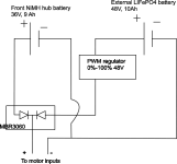
TidalForce.png
If you see any problem with this, do not hesitate to comment !

I ordered most of the components I need during the week-end, and I'm eager to get them to start work on my TF :)

Thanks to all contributors of this thread and especially Ambrose Liao and miro for their enthusiasm and lots of info provided for the TidalForce !

EDIT: Using PWM to reduce voltage doesn't work and the motor will still see some voltages superior to 48V, which is not good at all. I need to find a better way.
 
Mixing. 36v battery with a 48v battery is not a good idea. Simply add a 37V battery in parallel and save the complexity of your circuitry for another project. You could also just add the console jumper and use any 3rd party battery that can output 30A continuous.

http://ebikerider.blogspot.com/search?q=How+to+replace&m=1
 
Back
Top