casainho said:
Admiralrofl said:
I've been banging my head against the wall with trying to flash the NRF bootloader. I've 100% wired it correctly and have tried to flash 2 different NRF chips with a confirmed working stlinkv2 and every time I keep hitting this error. I've tried different OCD versions, I've updated the ST-link v2 to the latest firmware and even checked continuity on my solder joints to be sure everything is connected. What the hell am I doing wrong? below is the error I get in the CMD when I enter the command. Any help is greatly appreciated.
:\openocd\bin>openocd.exe -f ../share/openocd/scripts/interface/stlink.cfg -f ../share/openocd/scripts/target/nrf52.cfg -c "init" -c "halt" -c "nrf5 mass_erase" -c "exit"
Open On-Chip Debugger 0.11.0 (2021-11-18) [https://github.com/sysprogs/openocd]
Licensed under GNU GPL v2
libusb1 09e75e98b4d9ea7909e8837b7a3f00dda4589dc3
For bug reports, read
http://openocd.org/doc/doxygen/bugs.html
Info : auto-selecting first available session transport "hla_swd". To override use 'transport select <transport>'.
Info : The selected transport took over low-level target control. The results might differ compared to plain JTAG/SWD
nRF52 device has a CTRL-AP dedicated to recover the device from AP lock.
A high level adapter (like a ST-Link) you are currently using cannot access
the CTRL-AP so 'nrf52_recover' command will not work.
Do not enable UICR APPROTECT.
Info : clock speed 1000 kHz
Info : STLINK V2J39S7 (API v2) VID

ID 0483:3748
Info : Target voltage: 3.269960
Warn : target nrf52.cpu examination failed
Info : starting gdb server for nrf52.cpu on 3333
Info : Listening on port 3333 for gdb connections
Error: Target not examined yet
c:\openocd\bin>
c:\openocd\bin>
Try to run the same line but remove that init, halt and mass erase.
The way I do, is run OpenOCD without that commands, then on the OpenOCD sheel (using Telnet), I send that.commands one by one at a time and I get specific feedback for each one.
See the end of this page for the commands O send: https://opensourceebike.github.io/development/development-flash_and_debug_firmware.html
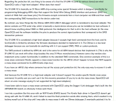
I'm running windows and setting up the visual studio code is a bit above my technical know-how. I did just try running the code without the init, halt and mass erase and i get this
C:\openocd\bin>openocd.exe -f ../share/openocd/scripts/interface/stlink.cfg -f ../share/openocd/scripts/target/nrf52.cfg
Open On-Chip Debugger 0.11.0 (2021-11-18) [https://github.com/sysprogs/openocd]
Licensed under GNU GPL v2
libusb1 09e75e98b4d9ea7909e8837b7a3f00dda4589dc3
For bug reports, read
http://openocd.org/doc/doxygen/bugs.html
Info : auto-selecting first available session transport "hla_swd". To override use 'transport select <transport>'.
Info : The selected transport took over low-level target control. The results might differ compared to plain JTAG/SWD
nRF52 device has a CTRL-AP dedicated to recover the device from AP lock.
A high level adapter (like a ST-Link) you are currently using cannot access
the CTRL-AP so 'nrf52_recover' command will not work.
Do not enable UICR APPROTECT.
Info : Listening on port 6666 for tcl connections
Info : Listening on port 4444 for telnet connections
Info : clock speed 1000 kHz
Info : STLINK V2J39S7 (API v2) VID
ID 0483:3748
Info : Target voltage: 3.269960
Warn : target nrf52.cpu examination failed
Info : starting gdb server for nrf52.cpu on 3333
Info : Listening on port 3333 for gdb connections
It just hangs here and doesnt do anything. Is there anyway to send those commands through the CMD prompt and avoid using visusal studio code?