Ebike finally died, need help finding out why

Kyle201

10 W
Joined
May 26, 2014
Messages
80
Location
Alberta, Canada
Hello folks.

So I come today with a problem. I built my first ebike several months ago, and have done almost 3000km on it so far without major issue, until it just died this week. The controller won't power on.

Some specs:
- Headway 15AH 24S battery
- 24S Headway BMS / PCM http://www.headway-headquarters.com/xji-24s-72v-50a-100a-pcm-special-order-only/
- Grinfineon 40A, 12 Fet Controller with on/off switch - Shunt modded to 62A
- Cycle Analyst V3
- Hardtail MTB frame, and I frequently go off-road.
- 50A littelfuse
- Key switch accessory

When it Happened:
After about 40km of very easy riding I went to go climb a short and slightly steep trail section, just a little bit rough and rooty. The bike bounced around a little as I started to go up and then barely before I even reached full power everything shut off, and the controller wouldn't start up anymore and still won't. Nothing was hot just barely warm.
Sometimes it will start up now with 2 light flashes, and the CA will almost show text for a split second. But usually only 1 red light on the controller flash, and just the CA backlight for a split second before it just shuts itself off again.

I inspected most of my wiring, at a glance nothing seems unusual, of course I will continue to look for something wrong in the wiring.

Some tests I did:
Mosfet test as illustrated on ebikes.ca
- Negative to all phases tested good
-Positive to phases tested strangely, giving me a high value (at MM set to 200K ohms) and this reading would slowly start to drop 0.1 per second or so. Not sure what that means.

Hooked up my 30v variable power supply to the controller, and it seemed to power on fine, CA powered on fine.

Tested battery voltages
- ~79V coming from the cell ends
- ~75V coming from the end of my wire harness at the bullet connectors that go to the controller

So what should I test or look for next? Just keep looking for a bad terminal or wire somewhere? Is it possible for a BMS sense wire to be broken if I'm still getting voltage like that at the end of my harness?

Any and all help appreciated.
 
you sould use a diode tester on the output mosfets to look at the body diodes.

no idea where the two different voltages are being measured if you say they should both be 79V.

did you test for 5V at the throttle to begin with?
 
Did you check the 50a little fuse? seems low to me.also what type of keyswitch is it?
 
Kyle201 said:
Tested battery voltages
- ~79V coming from the cell ends
- ~75V coming from the end of my wire harness at the bullet connectors that go to the controller
Problem is between the cell ends and controller. The voltage should be the same at both places. Maybe a very slight drop, but nothing close to 4V.
 
Icewrench said:
Maybe a connection issue?
Bms? Maybe a fused jumper to bypass the bms.

Seems like a connection issue.. probably try deeper inspections before trying a BMS bypass?

dnmun said:
you sould use a diode tester on the output mosfets to look at the body diodes.

no idea where the two different voltages are being measured if you say they should both be 79V.

did you test for 5V at the throttle to begin with?

Hmm, a diode tester.. I could try that I guess? Could a multimeter be used instead? I did try some mosfet testing already as well.
I do think the differing voltages are a good clue here.

beast775 said:
Did you check the 50a little fuse? seems low to me.also what type of keyswitch is it?

Yes I replaced it with a 60a fuse to no effect. The keyswitch is I believe the one crystalyte sells, perhaps it's the key switch causing a problem, causing the voltage drop between cell ends and harness terminals?

wesnewell said:
Kyle201 said:
Tested battery voltages
- ~79V coming from the cell ends
- ~75V coming from the end of my wire harness at the bullet connectors that go to the controller
Problem is between the cell ends and controller. The voltage should be the same at both places. Maybe a very slight drop, but nothing close to 4V.

Yup, that is a big drop it seems... so I should probably dismantle my harness and check for a bad connector then? Remove all heat shrinks etc...
 
Kyle201 said:
Yup, that is a big drop it seems... so I should probably dismantle my harness and check for a bad connector then? Remove all heat shrinks etc...
For a 4V loss, the harness would have to be 10' of 30wg wire with a 2A load. And there's no load if not connected to controller, so even with tiny 30awg wire there should be no drop at all. So there's definitely a problem in your harness somewhere. Fuse, connector, wire cold solder joint, something.
 
dnmun said:
you sould use a diode tester on the output mosfets to look at the body diodes.

I'm having a similar issue as Kyle201 and getting the same type of readings. I was wondering if they were polarity sensitive as mine read open one way and gave the variable readings described above the other. Could you tell us if a diode test is still done between Pos. wire and the phase wires and what kind of readings you would expect. Mine blocks pos to neg on phase wires but only after getting a reading for a few seconds.
 
Sounds like the BMS is cutting off. Try measuring the individual cell voltages at the BMS if possible.
 
fechter said:
Sounds like the BMS is cutting off. Try measuring the individual cell voltages at the BMS if possible.

I think it is the BMS.

I disconnected my accessory harness (fuse, keyswitch, charger port) and measured the voltage just from the main battery POS out and BMS neg out, and the voltage reading was the same low reading at 75.5, while still 79.5 at the cell ends.

So I tried to measure the individual voltages, how is that done exactly? I unplugged the sense harness from the BMS, and tried measuring between each positive cell pin hole, but what do I measure as the ground? I tried the BMS neg out, and also the negative sense pin hole, but it gives me the full pack voltage up to that cell is that right? Or how do I get the actual invividual cell voltages?
 
Probing each side by side wire at the plug will give individul cell voltage.
Be careful to avoid sparks by not crossing the meter leads.

Using pack neg as a common measuring point and moving the pos test lead in sequence should show a step up in voltage as you move along. Then a bit of math will reveal individual cell bank voltage.
 
Okay ! So I tested every individual cell voltage, and they are all within 0.1v of eachother, all 3.2-3.3V. So seems the battery is okay.

So what else could be wrong with the BMS to cause the 4V drop?

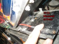
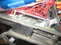
Here's some pics as requested

IMG_2900.JPG
View attachment 2
IMG_2902.JPG
IMG_2903.JPG
 
My guess would be one of the balancing wires that goes from the pack to the BMS came loose. This will make the BMS think a cell is out of range and shut down. Measuring them at the BMS will likely find a loose wire if there is one. The wire might look OK but have a bad connection.

If the BMS senses any cell out of acceptable range it will shut off the pack.
 
fechter said:
My guess would be one of the balancing wires that goes from the pack to the BMS came loose. This will make the BMS think a cell is out of range and shut down. Measuring them at the BMS will likely find a loose wire if there is one. The wire might look OK but have a bad connection.

If the BMS senses any cell out of acceptable range it will shut off the pack.

Right, but I tested each cell through the BMS's sense harness... and they all tested fine to be a proper voltage, wouldn't that mean every sense wire is getting a good connection?

Icewrench said:
Check all the cell screws to be sure none are loose.
Work slow avoid sparks. :shock:

Thinking this may be it... probably have to pull all the cells out and check for loose screws, pain in the ass. I've had the sparks a few times already building the pack :shock: exciting. Also shorted my main power terminals from the battery by accident once, good thing I had a fuse..
 
if you blew the fuse on the output when you have a BMS then you need to replace that BMS. it is not functioning. a BMS will turn off before a fuse can blow.

put a resistor across the 75V and see if the voltage drops to 0V. can you get the BMS out to where it can be analyzed?

if you had sparks when building it and you shorted out the shunt transistor on any channel then that channel will drain down to 0V and shut off the BMS.
 
Kyle201 said:
Right, but I tested each cell through the BMS's sense harness... and they all tested fine to be a proper voltage, wouldn't that mean every sense wire is getting a good connection?

Yes, that should mean they're all OK.

Try what dnmun suggested with some kind of resistor on the output of the BMS and see if the voltage drops to near zero. If you have a 1k lying around, it should be in the ballpark. Otherwise an incandescent light bulb is a pretty safe load.

If the voltage drops out with load, then the BMS is in some kind of protect mode. It can be pretty difficult to troubleshoot the board if all the sense wires have the correct voltages. It may be easier to just get a new BMS. Normally most problems are not the board but the connections somewhere.

Assuming it was working for a while and just quit, something failed somewhere, but there is usually a reason.
 
dnmun said:
if you blew the fuse on the output when you have a BMS then you need to replace that BMS. it is not functioning. a BMS will turn off before a fuse can blow.

put a resistor across the 75V and see if the voltage drops to 0V. can you get the BMS out to where it can be analyzed?

if you had sparks when building it and you shorted out the shunt transistor on any channel then that channel will drain down to 0V and shut off the BMS.

Yeah maybe that's the case... that was a while ago before this happened, exploded my bullet connectors. I was also told by the headway support that it is not an actual BMS as it doesn't balance constantly, only at the end of charge, so it's a PCM. Maybe that makes no difference in this case, and it should stop a dead short still?

So I went and picked up a few 1k ohm resisters (2% 1/4w, if that's relevant). So basically I'm just trying to short it out again with the resistor to see if it shuts off? Should I do it at the end of my wire harness with the fuse, or keep that disconnected and do it straight from the BMS neg/ battery positive wire?

I'll test with the resistor later today.
 
the 75V on the output may be leaking somehow through the transistors or around them so the resistor allows the voltage to be drained off. you coulda used a light bulb and the resistor value is not the issue.

if the BMS is turned on then the voltage will remain at the 75V instead of dropping to 0V.

but you need to be able to test the BMS so it needs to be opened or pulled out to where you can take pictures of it and measure the voltages.

just measuring gate voltages of the mosfets woulda told you that already without having to go buy a resistor.
 
dnmun said:
the 75V on the output may be leaking somehow through the transistors or around them so the resistor allows the voltage to be drained off. you coulda used a light bulb and the resistor value is not the issue.

if the BMS is turned on then the voltage will remain at the 75V instead of dropping to 0V.

but you need to be able to test the BMS so it needs to be opened or pulled out to where you can take pictures of it and measure the voltages.

just measuring gate voltages of the mosfets woulda told you that already without having to go buy a resistor.

Okay, it just seemed like it would be simpler to hook up the resistor to my connectors than a light bulb. They're cheap at a store close by, so...

I should be able to remove the BMS from the box easy enough by unplugging everything from it.
 
Suppose one couldn't. My sense harness connectors definitely won't reach outside the box, so... what tests would even require the BMS to be removed completely? I could remove it to take pics at least, if necessary.... seems I'm just going to have to replace it or run without it though.
 
Ok... so.

I have the sense harness completely unplugged from the BMS, and it still read 75.5-75.6 volts from it. I put the resistor across that, and the voltage read as 1.7V. Then I measured again without it and now it's 75.7V, so it went up 0.1V after that.... if that means anything.

Is it even worth it to try and diagnose this any further?

It's definitely the BMS it would seem, should I just replace it? I was thinking of finding a different one to try, since this one didn't last very long, and is expensive (almost $200 shipped...), but then I'd have to rewire all my sense connections instead of just swapping a new one in, since it looks like other BMS's have different harness connector layouts. Though I'd rather fix this one if it's even feasible.
 
Back
Top