
You are using an out of date browser. It may not display this or other websites correctly.
You should upgrade or use an alternative browser.
You should upgrade or use an alternative browser.
Eric's Project #002
- Thread starter Beagle123
- Start date
Malcolm
10 kW
Thanks Richard.
The obvious drawback to parallel charging is managing the series-parallel switch. But for my planned 12s pack I think I can do that fairly easily with a 25-pin military chassis socket and a couple of matching plugs, one wired with series jumpers, the other wired with parallel jumpers. I'm going to give it a try anyway. I've just bought a used 5V 30A power supply with ±10% voltage adjustment. Am I right in thinking I can put a Schottky diode in line with the power supply to drop the voltage about 0.5-1V?
EDIT: Just found out that Schottky diodes have lower than usual resistance, so I guess I can just put a few standard 5A diodes in parallel to drop the voltage to the required range.
EDIT 2: Just found the answer a page up. Thanks again Richard!
fechter said:Any power supply with a voltage trim adjustment would be easier to hack, since the adjustment is obvious. If the pot does not provide enough range, it is easy to extend the range by adding a resistor in series with one side of it.
vanilla ice
1 MW
I've got 10 old pc power supplies with 5v output in waiting till you guys to figure this out!
Malcolm said:EDIT: Just found out that Schottky diodes have lower than usual resistance, so I guess I can just put a few standard 5A diodes in parallel to drop the voltage to the required range.
Standard diodes don't play nice when paralleled. They tend to current hog since the voltage drop decreases with temperature. It would be better to get one big diode.
If your supply is adjustable +/- 10%, it might be easy to change a resistor to extend the adjustment range. Just trace the connections that go to the adjustment pot. They will most likely lead to fixed resistors.
Beagle123
10 kW
Malcolm said:I like the idea of your parallel charging arrangement, it's nice and simple.
What type of component is the "current sensor" shown in your wiring diagram?
Hi Malcolm:
I'm using the 50 amp version of the sensor fetcher posted. There are dozens of varieties at digikey.com.
I like that its simple too. However, I think the biggest benefits are that the batteries are balanced every time you charge, and its maintainable: You can easily find and replace bad batteries in the pack. I think too much attention is paid to graphs of cell performance. I"d like to see a graph for the whole bike. The performance would be great until a cell stated to falter, then the whole bike would plunge. Or maybe we should make a graph of the number of potential problems vs likelyhood of finding the problem.
As far as chargers go, I like the 400 amp model. Its adjustable to 4-6v and the current is adjustable too.
http://cgi.ebay.com/ws/eBayISAPI.dll?ViewItem&rd=1&item=300148554794&ssPageName=STRK:MEWA:IT&ih=020
It might work well for your bike, malcolm if lead-acid uses cccv, which I think it does.
The obvious drawback to parallel charging is managing the series-parallel switch. But for my planned 12s pack I think I can do that fairly easily with a 25-pin military chassis socket and a couple of matching plugs, one wired with series jumpers, the other wired with parallel jumpers.
Please tell me about these plugs!?!? I think you're absolutely right, that the big hurdle is the series/parallel switch. I'm using a block of andersens connectors as pictured above. Can these militartary plugs handle 50 amps? Where can I see them? Do I have to join the military to get them?
Please tell me more. What Plugs? Jumpers? Where? When? How?
Also, I have good news: you can do more than 12 batteries in series with a 25 pin plug. You can do 24 batteries in series using my design as described earlier. Imagine a 96v bike that uses the 400 amp charger pictured above. Sounds good?
RLT
10 kW
I beleive that NIMh has pulses in the current when charging, but don't quote me.
I know that NiMH battery chargers are supposed to be charged with dedicated chargers, but I have been charging 3 cell packs for some of my various custom LED lights using just plain old 4V / 75mA "wall warts" for years. They seem to 'terminate' at 4.18 to 4.23 V no matter how long (days, even weeks, when I forget to unplug them)
Only had one pack go bad on me so far, and the batteries in that were old surplus 4/3A size, of questionable quality in the first place. Of course with that low a trickle charge, would be hard to ruin anything.
I was just thinking I could use a faster 'brute force' charging system on them if I didn't have to worry about over charging them, and your circuit would probably do the job.
Yeah, solid state relays are handy. I use one for the foot control for the AC 'welder', home-made kiln temperature controllers etc. Recently found an inexpensive source for new ones that seem to be cheaper than buying used ones from the surplus places. I'm going to order a few extra for myself once I get the funds in my PayPal account rebuilt. It is in China though, so it will take a while to get them, and who knows what quality they are. I'll provide the link to the source if anyone is interested.
Malcolm
10 kW
Beagle123 said:Please tell me about these plugs!?!? I think you're absolutely right, that the big hurdle is the series/parallel switch. I'm using a block of andersens connectors as pictured above. Can these militartary plugs handle 50 amps? Where can I see them? Do I have to join the military to get them?
Please tell me more. What Plugs? Jumpers? Where? When? How?
I meant plugs like the one shown at the top of this thread http://endless-sphere.com/forums/viewtopic.php?t=2621
They're expensive to buy new, but you can sometimes find surplus ones cheap. I don't think you'll find any multipin ones rated at 50 amps per pin. IMO this charging approach will only be practical for fairly low-current applications, otherwise the series-parallel switching arrangement becomes too cumbersome.
On my motorbike I use individual (isolated) 12V chargers permanently connected to each battery and wired to a single mains plug. Dead easy.
Extending this approach to lithium gets messy and increases the risk of individual charger failure, so until a decent, inexpensive charging system becomes available I thought I'd have a go at parallel charging. The idea is to run (short) wires from the terminals on each cell to a multi-pin chassis socket. The cells themselves are not normally connected to each other. Instead, you have two plugs that fit each socket; one is wired with jumpers soldered between the pins to give a parallel configuration, and the other wired to give a series configuration. When you need to charge you just unplug the series-wired plug and plug in the parallel-wired plug, then charge at 3.7V. It's a bit Heath Robinson and has definite limitations. The current draw in series is limited by the current rating of the connector pins, but in my case it's intended as a cheap way of charging and balancing a very small A123 pack that will have a low current draw. I probably won't use this method with the LifeBatt cells I've ordered. The same idea could be extended to your pack, but I think it'll be difficult to find the right connector.
RLT
10 kW
OK, Last thread hijacking, Eric. ")
I finally got the basics of the CD welder put together, and started a thread on it:
http://endless-sphere.com/forums/viewtopic.php?t=2633
Lots more to do, but it will give you an idea on what is possible to do 'on the cheap'.
Most of the info is on my own site right now, but I'll start putting some 'meat' ion it here at endless-sphere as soon as I get time.
Beagle123
10 kW
On my motorbike I use individual (isolated) 12V chargers permanently connected to each battery and wired to a single mains plug. Dead easy.
That's a very smart approach in my opinion.
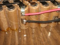
Pics of My Batteries Just in:
Mike at bigerc.com just sent me pictures of my batteries. He spot welded them into 14 packs of 6 cells each. His work looks great.
Attachments


i have not been paying attention much since we moved, but i finally found some time to catch up, and beagle123 asked me a couple of weeks ago to respond in this thread to the question of charging serial strings with multiple chargers. sorry if the question has been answered,but i am not up to reading all the threads i missed.
my experience has been that the negative output of the charger is almost always tied to the ground (round) pin of a 3 terminal 110v connector, so if you try to charge a 24v pack with 2 12v grounded chargers you will short out the first pack. the solution is to disconnect the ground terminal (there are adapters that do this or just cut it off. you do however still need to make sure the metal cases of the chargers do not contact each other, as they are always connected to ground in UL approved devices.
my experience has been that the negative output of the charger is almost always tied to the ground (round) pin of a 3 terminal 110v connector, so if you try to charge a 24v pack with 2 12v grounded chargers you will short out the first pack. the solution is to disconnect the ground terminal (there are adapters that do this or just cut it off. you do however still need to make sure the metal cases of the chargers do not contact each other, as they are always connected to ground in UL approved devices.
Beagle123
10 kW
Pictures of Batteries
MIke at bigerc.com sent these pictures of my batteries. We had to weld them so the tops and bottoms are flat in order to be able to stack them insside the battery box.
These will make a 6p, 14s pack. 54v, 18ah.
MIke at bigerc.com sent these pictures of my batteries. We had to weld them so the tops and bottoms are flat in order to be able to stack them insside the battery box.
These will make a 6p, 14s pack. 54v, 18ah.
Attachments


TylerDurden
100 GW
Them is purdy.... great pix Beag.
Beagle123
10 kW
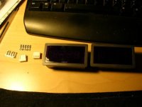
Just got my Dashboard.
I just received a volt meter and amp meter from ebay. I need to have a voltmeter on the bike because I don't plan to use a BMS. I'm planning on watching the overall voltage, and simply never letting it drop below 3.0v per cell.
Here are the auctions:
http://cgi.ebay.com/ws/eBayISAPI.dll?ViewItem&rd=1&item=140176764939&ssPageName=STRK:MEWN:IT&ih=004
http://cgi.ebay.com/ws/eBayISAPI.dll?ViewItem&rd=1&item=140177952783&ssPageName=STRK:MEWN:IT&ih=004
I have a question about them: I need to connect a 5v power supply to each of these units to power them. Is there a way to use the 60v battery power? Is there a 5v voltage regulator that will take 60v? If I use a battery (i.e. 9v) with a voltage regulator, do I need to use additional resistors to limit current? If you hook up a 5v battery, would current just flow through this thing and burn it out? In short, how do you power these things?
Also, I've never used those little, white, 5-pin connectors before. I'm assuming that you snip-off each of those little silver pins, then insert a thin wire inbetween the metal tabs. Then bend the tabs over the wire to hold it while you add a tiny dab of solder. Is that right?
Then, I'm guessing that you insert the little metal ends into the connector so that the pins contact the rounded parts of the metal ends? I don't quite know how to describe it. I'd usually just try it except I don't want to ruin them, I don't have replacements.
Attachments
vanilla ice
1 MW
Could you not just power it with a single 3.7v cell? Or three nicad AA bats?
Those meters look sweet man. Here's the meter from sciplus I just ordered for mine:
http://www.sciplus.com/itm_photos/93148.jpg
Those meters look sweet man. Here's the meter from sciplus I just ordered for mine:
http://www.sciplus.com/itm_photos/93148.jpg
The connector pins are designed to be crimped with a special tool. I have one. Very expensive.
Without the special tool, you can crimp it with needle nose pliers, then solder the wire to the pin. Be sure you don't let the solder run down to the contact area. After attaching the pin to the wire, it gets inserted into the connector body.
Those run on 5v. If you have a 5v battery, it would run directly off it with no resistor.
You could use a 9v battery and a 7805 regulator.
You can't power it from the main pack directly. The power and measurment inputs are not isolated. If you found a very small isolated dc-dc converter, that would work.
You could probably use an old cell phone charger with a 5v output. Something like an Ipod charger might work too. Any small switching mode power supply with a 5v output should do it.
vanilla ice
1 MW
Or $pend more on ebay...
http://cgi.ebay.com/ws/eBayISAPI.dll?ViewItem&item=250194326969
Or better than that one, spend the extra few bucks for the big capacity on the one the diggy diggy DOC found..
http://cgi.ebay.com/ws/eBayISAPI.dll?ViewItem&item=3872866587
http://cgi.ebay.com/ws/eBayISAPI.dll?ViewItem&item=250194326969
Or better than that one, spend the extra few bucks for the big capacity on the one the diggy diggy DOC found..
http://cgi.ebay.com/ws/eBayISAPI.dll?ViewItem&item=3872866587
Beagle123
10 kW
Thanks for the info.
I can also use the 4v battery for my headlights. Would that work?
vanilla ice
1 MW
That sounds like a better idea.
I bet one of these would work:
http://www.allelectronics.com/cgi-bin/item/PS-533/480/5.2_VDC_1_AMP_SWITCHING_SUPPLY_.html
Compact, wall plug-in switching power supply. Input: 100-240 Vac, Output: 5.2Vdc, 1 Amp. New unit, but output plug has been cut off of cord. Minimum cord length, 4 ft.
CAT# PS-533
Your Price: $4.00 each

http://www.allelectronics.com/cgi-bin/item/PS-533/480/5.2_VDC_1_AMP_SWITCHING_SUPPLY_.html
Compact, wall plug-in switching power supply. Input: 100-240 Vac, Output: 5.2Vdc, 1 Amp. New unit, but output plug has been cut off of cord. Minimum cord length, 4 ft.
CAT# PS-533
Your Price: $4.00 each
Beagle123
10 kW
That would work fine. Now I just have to install a 110v outlet onto my bike.
There's a very good chance those will run fine from 60vdc.
Johnbear
10 kW
Looks great, you are a pretty resourceful guy to get all of this done. I am in Vancouver BC, I don't think anyone in this city spot welds batteries. What does it cost if you don't mind me asking?
Thanks.
Thanks.
Beagle123
10 kW
Fetcher: that's very interesting. I may try to use a 4v source from my headlamp first. If that doesn't work, I'll give it a try. For $4 the price is right.
Hi JohnBear: I paid $360 to get them welded. The batteries cost $1400 for the Milwaukee packs. Total=$1760 I'd have to say that I might reconsider my options if I were to do this again.
There's a thread for a $100 homebrew welder taht looks really good. I'd consider that.
Hi JohnBear: I paid $360 to get them welded. The batteries cost $1400 for the Milwaukee packs. Total=$1760 I'd have to say that I might reconsider my options if I were to do this again.
There's a thread for a $100 homebrew welder taht looks really good. I'd consider that.
safe
1 GW
- Joined
- Dec 22, 2006
- Messages
- 5,681
Beagle123 said:I paid $360 to get them welded. The batteries cost $1400 for the Milwaukee packs.
My hope is to achieve bike performance that exceeds 40 mph with a
battery that costs LESS than what you spent on welding. I can't believe
how much people are spending on batteries.
vanilla ice
1 MW
Its all relative. I think $264 is way too much.
Similar threads
- Replies
- 6
- Views
- 1,124
- Replies
- 10
- Views
- 569