High power RC motor and drive unit production

MitchJi said:
Hi Gary,

How do you plan to mount it on the 1-3/8" bearing tube?

I can't find 1/16" wall tubing online. What I did find (at McMasters) is:
Wall Thickness .065"
Inside Diameter 1.37"
Outside Diameter 1-1/2"

I think, if necessary, you can remove the .025 with some emery cloth, on a shaft or stick, while rotating the tubing in a drill.

Actually, I think 2-1/2 thousandths is probably close enough. :wink: There needs to be a slot cut anyway. I should get the stem and the tubing tomorrow, so I'll give it a try.

-- Gary
 
MitchJi said:
I can't find 1/16" wall tubing online. What I did find (at McMasters) is:
Wall Thickness .065"
Inside Diameter 1.37"
Outside Diameter 1-1/2"

I think, if necessary, you can remove the .025 with some emery cloth, on a shaft or stick, while rotating the tubing in a drill.
EDIT: Should be .0025

Hi Mitch,

.065" is close enough. No need to remove anything, in this case. You slit the shim tube lengthwise (one saw cut) to enable it to fit, and transfer the clamping force to, the bearing tube.
 
David/CNCAddict,

Can you let us know about motor status, or is that on hold for now?

Thanks.
 
Miles said:
MitchJi said:
I can't find 1/16" wall tubing online. What I did find (at McMasters) is:
Wall Thickness .065"
Inside Diameter 1.37"
Outside Diameter 1-1/2"

I think, if necessary, you can remove the .025 with some emery cloth, on a shaft or stick, while rotating the tubing in a drill.
EDIT: Should be .0025

Hi Mitch,

.065" is close enough. No need to remove anything, in this case. You slit the shim tube lengthwise (one saw cut) to enable it to fit, and transfer the clamping force to, the bearing tube.


If you are looking for tubing on line, look at Aircraft Spruce, they supply many diffenent sizes and various wall thickness in 6061 aluminum and in 4130 steel...will also cut small pieces for orders...they typically supply experimental airplane builders

Britt
 
I got the tubing, but no stem yet. I hate that Jenson lets you order something, says it is in stock, and then half the order is backordered. The is the 3rd time in a row, so I won't order from them again. :evil:

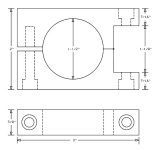
So, I'm going forward with the new clamp idea. I didn't have time to learn any new software, so no 3D, but here is what I'm going to try and make:

Frame Clamp.png


Pretty simple, really. I have a hole saw bit to drill out the big hole. The rest is simple straight cuts, and then drilling some holes and tapping one. I think I can manage this, but we'll see. :roll:

-- Gary
 
Hi Gary,

Wouldn't it be easier to drill the hole on the left of your drawing all the way through and use a bolt and nut?
 
I hate that Jenson lets you order something, says it is in stock, and then half the order is backordered. The is the 3rd time in a row, so I won't order from them again. :evil:

I'm glad you mention this, I just ordered a freewheel from Jenson and they sent me the wrong one, then I ordered a different freewheel and they sent me the wrong one again :shock: so I bought one from universal cycles.
 
GGoodrum said:
I got the tubing, but no stem yet. I hate that Jenson lets you order something, says it is in stock, and then half the order is backordered. The is the 3rd time in a row, so I won't order from them again. :evil:

So, I'm going forward with the new clamp idea. I didn't have time to learn any new software, so no 3D, but here is what I'm going to try and make:


Pretty simple, really. I have a hole saw bit to drill out the big hole. The rest is simple straight cuts, and then drilling some holes and tapping one. I think I can manage this, but we'll see. :roll:

-- Gary

That is the exact clamp I am using on my PK. :mrgreen:

Matt
 
MitchJi said:
Hi Gary,

Wouldn't it be easier to drill the hole on the left of your drawing all the way through and use a bolt and nut?

Yeah, it probably would. I might just end up doing that, but maybe cut out a a recess so the bolt and nut don't stick out.

-- Gary
 
Not a machinist by any stretch of the imagination, but it seems to me you could make this as a blank, with a pilot hole drilled right in the middle. Then when someone wants a clamp for an odd size, you can drill it to the proper size and it's done. One size fits all, sort of.

Only thing is, I think my tube is over 2" so your blank would probably be too small.
 
Hi Gary,

As drawn the split is perpendicular to the bottom of the foot. I think that will complicate (probably not for Matt) getting a snug fit on both the foot and the tube.

So you might want to consider splitting the mount parallel to the bottom of the foot. If I did that I would make the mount wide enough that the vertical bolts could be drilled all the way through (to shoulders next to the foot bolts) so that threading the aluminum isn't required.

:) Are you going to make a small run and sell them? :)
 
Gary's layout is very good. What you want is the foot notch to be slightly larger than the foot itself. That way there is a gap to be snugged. That is the way my PK ripper is.

1clue,

Yes, I considered a generic clamp that can be bored. I can look into that (making a number of them). The best option still seems to be a somewhat flexible clamp that can alter in shape to fit the tube.

Matt
 
MitchJi said:
:) Are you going to make a small run and sell them? :)

Ha! No, I'll be lucky to be able to do a couple of these and still end up with all my fingers and toes! :mrgreen: I'll leave the "production" to Matt, for whatever he ultimately comes up with as a solution.

To me, a stem-like design, which replaces the foot altogether, is the "ultimate" solution for tube installations. Matt will have to charge as much, just for the foot adapters, as it costs for a nice stem (I paid $24...), so I'm wondering if it wouldn't be cheaper to design and do a CNC'd version for the largest size (1-1/2"?), and then use the shim/tubing trick to cover smaller tube diameters.

In any case, I will attempt to do these couple of adapters, but I'd forgoe that effort in a heartbeat if Matt would do them. :)

-- Gary
 
Just as I was getting ready to start making one of the adapters, the 1.5" stem showed up. I switched horses and cut a section of the 1.5" O.D/.049" wall aluminum tube I got from McMasters. with a slot cut in the tube, it was a perfect fit:

Tube%20Clamp-01.jpg


Tube%20Clamp-02.jpg


Tube%20Clamp-03.jpg


It ended up being a very good fit on the bearing tube, and as such a viable "foot" replacement. Here's a quick and dirty install on one of my bikes, just to check locations. The seat tube on this one is a bit oversized, but it would still work just fine:

Tube%20Clamp-05.jpg


Tube%20Clamp-06.jpg


Today I'm going to play with trying this on for size on my other bikes. I'll post some more pics later.

-- Gary
 
Hi Gary,

Excellent! :D :D :D :D :D :D
 
Looks cool!

I have a decent somewhat universal clamp figured out. My drive production run #2 is slated to hit the CNC Tuesday. The new clamps will be made then too.

I love it, Gary!

Matt
 
Hi Matt,

recumpence said:
I have a decent somewhat universal clamp figured out. My drive production run #2 is slated to hit the CNC Tuesday. The new clamps will be made then too.

Matt

What is the range of sizes of down-tubes that the clamps accommodate?

Will they work with non-round down-tubes (like D's Kona)?

You might want to make a few extra for use with some of the V1 drives.

Thanks!

Mitch
 
I am purposely making the V2 drives the same as the V1s for reverse compatability. :wink:

I am just now gathering the information I need on the size range required. It looks like I may have to make a small and large version of the mount clamps. They should be somewhat compatible with non-round tubes. Picture a CNC machined aluminum hose clamp that the wrap around "Ribbon" is 3/4 inch wide and (maybe) 1/8 inch thick. That ribbon should be flexible enough to squish around subtle differences in non-round tubes. I have not tried this before, though. So, I have to machine one to test first. I see no reason it would not work, though.

Matt
 
Awesome,

looking forward to seeing what you come up with there Matt.
Another couple of weeks and we should start seeing these bikes in action, i'm wondering what Ypedal is up to?


Cheers,

D
 
lol,

well my guess is he's still sitting looking at it then looking at the norco, look at it again, look at the norco :lol:

Cheers,
D
 
OK, the next batch of drives is in the CNC being cut as I type.

Now, I went over the drive clamps I have designed with Dave (the CNC machinist). We went over and over them and have a design that should be boiled down to the best option.

Once the drives are done (in a couple days) we will prototype a couple clamps to test. Then we will iron out any kinks a produce some.

The cost is still sky high on these crazy things because there are 4 separate CNC machined pieces to make the two clamps for one drive. The material cost is about $20 for the set plus machining time. These crazy things look like they will cost me as much as $100 per complete set to have made! Dave and I have gone over this from every angle immaginable. There just is no way to do this cheap without it being hack.

Anyway, I will make a few and show you............

Matt
 
Back
Top