**Important** reality check on motor, voltage, current etc.

donob08 said:
I have one last idea I keep forgetting to offer. If the Cycle Analyst had an input for throttle voltage, throttle position would be a good indicator of the value of D in the PWM control

Unless it is current limiting. If it is current limiting and the cycle-analyst knows the battery current, the motor resistance, the speed, the motor's k constant, etc., then it could predict the phase currents in the moment. But, alas, it doesn't know all of that. (And the margin of error would probably be uncomfortably large)
 
I think the main variable would be stator diameter to achieve greater flux and torque. Unless you're talking real specialty motors, it'll usually be cheap soft iron rather than any sort of specialty magnetic material. A larger stator with more cross-sectional area can carry more flux. Also, stronger magnets will always produce more torque. I don't think hub motors typically use the strongest grade of magnets, so if you can find the right size and shape you can probably upgrade those. I'm pretty sure stronger magnets would also give higher efficiency, since you'd get more torque per amp.

I suspect, but do not know for certain, that the ebikes.ca simulator does not include magnetic saturation. Justin or maybe one of the other experts might be able to say for certain. I suspect it does not just because that would require quite a bit of effort to properly simulate the magnetic effects. It's certainly possible, but would require assuming nonlinear inductance and so forth.
 
Stronger magnets should behave just the same as a reduced flux gap AFAIK. You drop Kv, boost Kt, BEMF builds faster with motor speed, and your eddy losses now increase faster with RPM by the same rate of the increase in flux (the downside of less gap or stronger magnets).

The boost in Kt should mean the same saturated flux density on the tooth will be able to produce a higher rotor torque as I'm seeing it, but I'm far from an expert.
 
I'm also not a motor expert, but I think Miles and LFP are both partially right. Increasing the flux due to permanent magnets should increase torque no matter what's occurring with the induced field. However, I think saturation may also play some part. The magnets rely on the stator iron for part of the flux return path, so saturation should have some effect. It would take pretty careful analysis to figure out the exact effects.

I think the general principle is valid, that stronger magnets will produce more torque. But I suspect it won't be one-for-one.
 
Thank you for that additional insight Rick.

I was thinking of them as separate flux entities :oops: , but you're right, they do use the tooth for a return path. Miles might be looking at things perfectly if the tip of the tooth is as flux saturated as it's going to get, then it may not matter (much) if you push the magnets closer and/or increase strength.
 
By changing the strength of the magnets wouldn't we risk changing the flux pattern to the worse resulting in a counter productive effect. eg My motors have quite a thick iron ring behind them, and the flux is all confined inside toward the stator. If I mounted stronger magnets and the flux started to flow outside the backing ring like it does on the small lightweight RC outrunners, I think it would result in some significant changes to the lines of magnetic flux inside and directed at the stator.

The 48 magnets in my hub motors are a pretty small standard size rectangle, so changing them would be fairly easy, but I'd only want to try it if I was pretty sure the change would be positive.

Another thought if stronger magnets can only make things better, since we're not so concerned with weight on a bike as for an RC plane, wouldn't it be a significant improvement to those outrunners to slide a tight fitting steel sleeve over the motor can to obtain the same effect as better magnets through better containment of the flux?

John
 
That's where we run into the down side of stronger magnets, like more eddy loss, cogging losses, etc.

If you could throw a magic magnet in there with infinite flux, then the motor wouldn't be able to even turn (infinite cogging torque, infinite eddy losses etc).

I think for most motors, the gains to be had from stronger magnets ranks pretty low on the overall performance side of things. In your particular situation of wanting to lower Kv, swapping all those magnets from whatever they are now (N-36? N-40?) to the best N-48 material you could buy would be kinda a really wimpy potential difference to make it worth the trouble IMO. If you could snap your fingers and make it happen instantly by magic, I would say go for it, but in real life, I think the effort vs reward on it would be very low.
 
Another problem with magnet strength is that the stronger it is, the closer it tends to hold it's flux to it's surface, potentially forcing airgaps to be smaller.
 
If we have sufficient info we could model the motor and see exactly what different changes would do. I have software that can do FEM analysis if other people can help supply information. An x5 series motor seems like it would be a good candidate. We can construct a 2D model across the cross section of the motor. Once we have a basic model, we can change the magnets or make other changes to see the results. I think I would be able to use the model to calculate the resulting torque to get a useful output. Since we should have some data on the standard configuration, that would let us see if the model is accurate.
 
Miles said:
liveforphysics said:
That's where we run into the down side of stronger magnets, like more eddy loss, cogging losses, etc.
Are there any losses due to cogging? I didn't think there were.

What causes the motor to slow down so quickly when it's unloaded? Are the bearings really that bad or is it mainly due to something else? I thought the main reason was due to cogging though it may be something else magnet related.
 
rhitee05 said:
If we have sufficient info we could model the motor and see exactly what different changes would do. I have software that can do FEM analysis if other people can help supply information. An x5 series motor seems like it would be a good candidate. We can construct a 2D model across the cross section of the motor. Once we have a basic model, we can change the magnets or make other changes to see the results. I think I would be able to use the model to calculate the resulting torque to get a useful output. Since we should have some data on the standard configuration, that would let us see if the model is accurate.

The X5's might be more difficult than many others, because they have fewer and curved magnets. Something I'd really like to try is replacing each of my magnets with a hallbach array so I could go with a very lightweight magnet retaining ring. If it would reasonably assure greater torque, that would be worth a shot, and since I have 5 comparative results is easy. One of the online stores has the correct size N42's that would double the thickness of my current magnets plus I'm sure a higher N rating at total cost of just $70 for the 240 magnets I'd need. To make the hallbachs, I think I figured out an easy method by sliding each rectangular mag into an aluminum channel to glue and clamp them in the correct orientation. Still tedious work, but not too bad if the channel idea works for making hallbach array assembly straightforward.
 
Miles said:
Different patterns of poles and nuts give greater or lesser cogging. Does this actually affect the rate at which they slow down?

Mine coast quite well, but pedal only at very low speed is a real bitch. So much so that I alternated between walking the bike and pedaling home when that controller blew the other day.
 
John in CR said:
The X5's might be more difficult than many others, because they have fewer and curved magnets. Something I'd really like to try is replacing each of my magnets with a hallbach array so I could go with a very lightweight magnet retaining ring.

We could model this as well, it's easy to set up almost any scenario once the structure is modeled. All I would need is the dimensions of the stator, magnets, and magnet ring. It'd be nice if we know what the materials are, but we can make a guess otherwise.
 
rhitee05 said:
We could model this as well, it's easy to set up almost any scenario once the structure is modeled. All I would need is the dimensions of the stator, magnets, and magnet ring. It'd be nice if we know what the materials are, but we can make a guess otherwise.
IIRC, DoctorBass or Hal posted an x5 modeled in CAD, but I can't seem to find it on ES. It might have gotten lost.

Found this:
http://endless-sphere.com/forums/viewtopic.php?p=59999#p59999
 
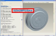
Here it is :wink: I think it was Hall that posted it .

Doc
 

Attachments

  • x5area2.jpg
    x5area2.jpg
    43.7 KB · Views: 1,822
That's nice CAD work, but unfortunately only seems to include the outer shell and axle. The stator and rotor magnet ring are the important bits for magnetic modeling.
 
swbluto said:
What causes the motor to slow down so quickly when it's unloaded? Are the bearings really that bad or is it mainly due to something else? I thought the main reason was due to cogging though it may be something else magnet related.

Actual cogging torque ripple as Miles pointed out should somewhat cancel out in the end, but I think when most people use the term 'cogging torque' they mean all the associated losses for turning a motor over, not just the changing reluctance torque from magnets aligning with the poles.

In the case of hub motors, the major source of resistance to spinning would seem to be hysteresis in the iron core. Each time the magnets pass over a pole they cause flip in the direction of the magnetic field in the stator, and the resulting hysteresis loss would produce a more or less steady resistance force regardless of speed.

The other losses from induced eddy currents and wind drag would both in theory increase with the square of motor RPM, resulting in an upwards curving torque vs. rpm graph. But that's not what we see at least at the wheel speeds on a bicycle.

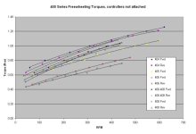
Here are some directly measured values for the no-load torque required to spin a variety of Crystalyte 400 hub motors that I compiled a few years ago:
400 Series Spin Torque2.jpg

Quite a lot of variation even with the same motor type! (the windings shouldn't have anything to do with this, but were just used to identify the hubs)

Most other types of motors also show a pretty close to linear with slight downwards curving torque vs. rpm relationship over the speed range of interest. It doesn't totally match with the theory, which should be a constant value from hysteresis, plus a quadratic term from eddie currents and windage. Perhaps someone here might be able to shed some light on this detail?

-Justin
 
Justin, thanks for the post. My motors cog enough that my out of shape self can't maintain a pedaling speed in the event of an electronic failure, however, my bike coasts pretty well when I let off the throttle. Now that I understand that the wall I'm against is mostly a straight and flat line, it really encourages me to get in better biking shape. Then even though I can't yet pedal assist due to gearing and high speeds, I have an achievable target for being able to truly have pedaling my bike as a backup. If cogging increase linearly with speed, then why try, but since it's relatively fixed in power I just need to be able to provide a bit more with my legs. My 2 most recent failures left me walking the bike after an extended flat or the slightest incline. Now that I know I just need a handful more watts of leg input for pedal only to be a reality, with a bit of exercise I know I can count on the leg power backup.

John
 
John in CR said:
Justin, thanks for the post. My motors cog enough that my out of shape self can't maintain a pedaling speed in the event of an electronic failure, however, my bike coasts pretty well when I let off the throttle. Now that I understand that the wall I'm against is mostly a straight and flat line, it really encourages me to get in better biking shape. Then even though I can't yet pedal assist due to gearing and high speeds, I have an achievable target for being able to truly have pedaling my bike as a backup. If cogging increase linearly with speed, then why try, but since it's relatively fixed in power I just need to be able to provide a bit more with my legs. My 2 most recent failures left me walking the bike after an extended flat or the slightest incline. Now that I know I just need a handful more watts of leg input for pedal only to be a reality, with a bit of exercise I know I can count on the leg power backup.

John


I will never forget us riding back from the dive shop together, me with the bee that stung me right in my nose while riding on the side of the freeway, and then later getting low on juice with one bike, and needing to do that crazy 1-handed buddy-ride-shoulder-tow manouver on the side of a highway with minimal room for bikes, and that crazy blistered sunburn. lol That was a pretty damn good time John. Trying to pedal that monster with no power assist felt like trying to pedal through deep sand.


justin_le said:
file.php


Quite a lot of variation even with the same motor type! (the windings shouldn't have anything to do with this, but were just used to identify the hubs)

Most other types of motors also show a pretty close to linear with slight downwards curving torque vs. rpm relationship over the speed range of interest. It doesn't totally match with the theory, which should be a constant value from hysteresis, plus a quadratic term from eddie currents and windage. Perhaps someone here might be able to shed some light on this detail?

-Justin

I've been scratching my head on this one... That sure isn't the signature of eddy current loss. I have a possible guess (kinda a crappy one, but a place to start perhaps). The BEMF currents get some loss from the termination against the other phases creating internal recirculting currents. It would explain at least some of the relationship between the winds and torque differences (which can't be from eddys of course).

I have a hunch that if the wye termination points were all snipped, the torque you're seeing would drop in a big way, and then follow something shaped more like a cubed function. What do you think?
 
Miles said:
Justin's "freewheeling torque" seems a much better descriptor than "cogging torque", which leads to endless confusion.....

Agreed. On paper, cogging losses are always suposed to perfectly balance out etc etc so they shouldn't be a loss at all (model assumes fixed constant rotor speed). If you read propaganda from folks doing coreless ironless motors, they always tend to come up with graphs showing "cogging loss" (or maybe just the inherent hysterisis loss from the field lines swapping in the rotor teeth?). Maybe just propaganda?

Also, as potential "cogging loss", anything that makes the rotor have rotational velocity fluctuations (maybe the torque ripple+ cogging vibrations) is going to involve the loss of energy. Of course as the rotor's polar moment relative to the delta-torque increases, this loss heads to zero.
 
"Cogging:

In a permanent magnet motors cogging torque manifests itself by the tendency of the rotor to align in a number of stable positions when unexcited. .......... Although cogging does not consume power and is not visible in the torque speed plot, under dynamic conditions it may cause undesirable speed pulsation and also may induce vibrations and acoustic noise.
"

Ref: http://www.20sim.com/webhelp/toolboxes/mechatronics_toolbox/servo_motor_editor/theory/torque_speed_plot/losses.htm
 
Back
Top