Inductance question when connecting 2 batteries in parallel using ideal diodes

kilou

10 W
Joined
Aug 25, 2014
Messages
87
Hi,

I'm interesting in connecting 2 36V Li-ion ebike batteries in parallel using ideal diodes (e.g. mosfets) for reverse current protection. I know that (in principle) ideal diodes are not needed if the two batteries are connected with the same state of charge. However I have to use diodes in my application because each battery is protected with its own BMS and both BMS don't let any charging current run from the discharge wires. Additionally, I'd like to use the batteries with slightly different state of charges so (ideal) diodes are required.

My question regards what happens in terms of inductance in the wiring when the motor is stopped and each battery is protected with its own ideal diode? My understanding is that, without the diodes, wire inductance is not really a problem as it would be smoothed out by each battery (although that is not really possible if the BMS does not allow the batteries to be charged through the discharge leads...). However, with the diodes, current cannot flow back to the batteries so would that create a voltage spike between the controller and the ideal diodes, possibly leading to premature failure of any of these?? If so, is there anything to prevent such voltage spike from happening, i.e. by using a flyback diode somewhere in the circuit? I'm mostly concerned by the inductance in the positive fat wire (between controller and diodes) seen on the image below.

Would such a system be reasonably safe? I'd possibly be adding additional fuses next to each battery but I'm not sure this would add much since the discharge has to handle 20A max while each battery is supposed to be charged at 4A max (so e.g. a 25A fuse suitable for discharge would not really protect anything in case one of the diode fails as the charging current would likely but much higher than 4A without the fuse blowing...)circuit.png
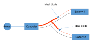
 
I'm mostly concerned by the inductance in the positive fat wire (between controller and diodes) seen on the image below.
Just to clarify, is the assumption that the fat wires are coiled, and if so how many loops/turns? Note that inductance on a straight conductor is zero or near zero.
 
Just to clarify, is the assumption that the fat wires are coiled, and if so how many loops/turns? Note that inductance on a straight conductor is zero or near zero.
No the fat wires are not coiled. Actually they are standard wires (same gauge as the other wires, AWG14) and are just fat for the purpose of illustration (section between controller and diodes). However the motor is coiled and I don't know how back EMF when the motor is turned off is passed beyond the controller, in the wiring and back to the diodes/batteries...

Note that the wiring length is close to 1m between controller and each battery. In the eskateboard world, I've read several posts of people warning that long wiring from battery to controller (e.g. VESC) would create large voltage spikes potentially frying the controllers. This happened without diodes by the way but it was related to wire inductance. Shorter wires between battery and controller was one solution to solve this. So I guess wire inductance still plays some role.
 
Last edited:
I would be more concerned about back EMF on fast downhills rising above the controller's component ratings. But that would be of concern even without the protective mosfets, if the BMS doesn't allow charging through the discharge wires. If I had a pack like that, I'd discharge directly from the cell pack leads to bypass the BMS's counterproductive nonsense.
 
Would such a system be reasonably safe?
Risks:

1) Regen will blow up the controller.
2) If you don't have regen but do have direct drive, if you go over base speed the voltage will climb and potentially damage things.

I'd add at least a zener clamp for this, and then monitor the zener. If it gets really hot then it's absorbing too much power, and you'll know you have to take additional precautions.
The bike has no regen and it's not a direct drive. It's a mid drive motor with a torque sensor. This is probably why the BMS does not allow charging through the discharge leads. So without regen and no direct drive, does it mean it's a safe setup? Is a zener clamp still required?

Where would you add the zener clamp on the circuit? Just after the controller? Any idea on how to choose the zener rating? Motor power peaks at about 600W, both batteries are 42V when fully charged.
 
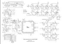
Here's a representative controller schematic. You can determine whether they've snubbed off the inductance on the phase drivers. I dunno. I had to worry about it at work 50 years ago for printhead drivers..


ku63_schematic.jpg
s
 
I don't have the skills to read such complex diagram unfortunately. However, it seems wire inductance can still cause issue. Here is what I came across:

"Adding wire length (inductance) in battery to controller wiring is very bad for the controller. It causes increased ripple in the capacitor bank currents and increased spikes in the FET voltages during switching, which causes capacitor and FET heating and reduces the FET voltage margins. FET voltage spikes can cause reduced device life or even rapid failure. Capacitors are not tolerant of heating and are easily damaged."

source
 
My Baserunner controller will turn itself off frequently and require an over voltage fault to be cleared via software suite if I plug it into a battery blender and go downhill. Amusingly, it doesn't support programming the the regen amount to 0 either.
 
True, there’s a huge thread on rcgroups on this subject. Keep wires as short as possible and as closely bundled together as possible, the wiring loop area sets the inductance created between battery and esc.
Any possibility wire length inductance (or voltage ripples) increases when using diodes or is it unrelated? It seems to me the current flowing through the whole battery wire would be "trapped" in a smaller portion, between the controller and the diode, when the motor shuts off...
 
Last edited:
Yes, i think you’re correct, it will be more of an issue but cannot really set it into proportions, not my expertise. I read a thread on rcgroups some years ago where there was spiking visible on a scope with a dual battery plus diode setup. But was it a stopper? Can’t remember.
 
Hi, kilou!

Using ideal diodes (e.g., MOSFETs) is a reasonable approach to paralleling the two batteries while preventing reverse current flow due to the individual battery management systems. However, you raise a valid concern about the inductance in the wiring, particularly the positive wire between the controller and ideal diodes.

When the motor is stopped, the inductance in this wire can indeed lead to a voltage spike across the ideal diodes as the current tries to abruptly stop flowing. This voltage spike could potentially damage the controller or ideal diode circuits.

To mitigate this, a flyback or freewheeling diode can be added across the motor terminals (parallel to the motor) to provide a path for the inductive current during the voltage spike. This diode would clamp the voltage spike to a safe level determined by the battery voltages.

Additionally, appropriately rated capacitors across the ideal diode outputs could help absorb and smooth out any remaining voltage spikes.

Overall, with proper component selection and the addition of a flyback diode across the motor, this parallel battery configuration using ideal diodes should be reasonably safe for your application. Monitoring and protecting against overcurrent conditions is still advisable.
 
Back
Top