Infineon controller REVIEW+tests with 18x IRFB4110

Jeremy, thanks for your calculation.. that make sense to me and this is also encuraging!! :mrgreen:

I also remembered by you that to paint the cover case in black would help!!.. that make the cover case like a black body!! a perfect heat exchanger!

I'll do some of the mod you suggested like the mica mod...

You know what..!! :mrgreen: this is my job to work with IR these last months..!!

I have a job as a optical technologist at INO... (http://www.INO.ca)

I work on a camera project for NASA and Argentina and (CSA) Canadian Space Agency that will go in a satellite to explore the temp of the earth and forest burn and ocean temperature change for climate change!!!

We built and test two Long Wave and Mid Wave camera for that..

They are the first IR camera in the world with these caracteristics that dont need any cooling inside!! great for satelite low power consumption!!! 3milion $ !!

So i know about black body science ! :mrgreen: 8)
Here is 2 recent articles: http://www.smartmoney.com/news/pr/?story=PR-20090317-001092-0945&hpadref=1

http://lejournaldequebec.canoe.ca/j...egional/archives/2009/03/20090317-195437.html

Curiouslu a black anodized finish give lower result than a normal blach paint.. I tested alot of balck coat during these last monmth for that project!!

Doc
 
wrobinson0413 said:
Hi Doc

Great pictures of your boards. I was examining the board layout and I noticed that you did not take a shot of the high side gate drivers that are under the electrolytic capacitors. Would you be able to lift one of the caps up and take a picture and post it. I am curious about what high side driver they decided to use? The lowside transistor driver isn't too surprising. Looking at the whole board, they really don't have very much on it. It must be very cheap to produce. Probably all the cost is in the mosfets and high side drivers anyways. Also, what is the overall length of the board? It seems to be very long.


I'll take a closer pics of the H and L side driver for you tonight :wink:

and take a measurement of the board dimensions :wink:

Doc
 
Hey Doc -can you post the link where you got the 18 Infineon without the Mosfets?

I might try it with 4115s at 40-50A and 120V (3 packs at 40V). My 5304 already gets warm with 80V and 40A.

Great work

DK
 
Doctorbass said:
The torque arms will be helpfull !!.. 8mm thick stainless !! wow!..

how much for identical torque arm? :mrgreen:
Hi Doc
sorry not to get back to you sooner on this, I design my own torque arms in turboCAD 15 deluxe this is a 3d cad tool and can output files compatable with the laser cutter's program that way I do all the design work all the cutters do is cut the metal.
i first build up in a cad file the dropout and then make sure it is correct bu printing out on paper and cutting out, once this is done it is simple to make the torque arm including making sure there is enough thread for the nut!
my latest design is a away from the normal type of torque arm instead of a 14mmhole with 10mm flats I did a dropout with a 15mm arc at the top like an open ended wrench made of 8mm there is no chance of the the flats on the axel spreading those arms to stop the motor coming off I have added a nut retainer to each arm.
they will be charginging about £30 for both arms and a pair of clamps. this company charge by the cut not by the hour as most laser cutters do I must of tried 10 before i found this company.

sending one over would be as much as you getting it cut localy, I will ask how much shipping to canada is though.

once you fit a new shunt and calibrate it so you what value it is, the method for calibration is not difficult I have one knuckles posted a picture of his, then all you do is calculate the diffrence between that and the standard shunt as a multiplier then you can program the controller and get a finished infineon of a lot more power than 57 amps which is the max at the moment, over 100amps would be possable.

Geoff
 
Deepkimchi said:
Hey Doc -can you post the link where you got the 18 Infineon without the Mosfets?

I might try it with 4115s at 40-50A and 120V (3 packs at 40V). My 5304 already gets warm with 80V and 40A.

Great work

DK
hi
with 4115's at 12v you will need to change the caps on that board for sure they are only good for 100v , if you are using a 5304 then you can have regen a custom resistor nsetup would be needed the regen is disabled at high voltades unless we fool the chip into thinking the voltage is a lot lower.

Geoff
 
Deepkimchi said:
Hey Doc -can you post the link where you got the 18 Infineon without the Mosfets?

I might try it with 4115s at 40-50A and 120V (3 packs at 40V). My 5304 already gets warm with 80V and 40A.

Great work

DK


I dont know if that's ok for Keywin to sale at large these board without mosfet. You should contact him and ask him directly. I'll PM you his Email. If it work for you, it cold work for someone else too. But i just want to ensure that Keywin feel ok with that.

Doc
 
geoff57 said:
Doctorbass said:
The torque arms will be helpfull !!.. 8mm thick stainless !! wow!..

how much for identical torque arm? :mrgreen:
Hi Doc
sorry not to get back to you sooner on this, I design my own torque arms in turboCAD 15 deluxe this is a 3d cad tool and can output files compatable with the laser cutter's program that way I do all the design work all the cutters do is cut the metal.
i first build up in a cad file the dropout and then make sure it is correct bu printing out on paper and cutting out, once this is done it is simple to make the torque arm including making sure there is enough thread for the nut!
my latest design is a away from the normal type of torque arm instead of a 14mmhole with 10mm flats I did a dropout with a 15mm arc at the top like an open ended wrench made of 8mm there is no chance of the the flats on the axel spreading those arms to stop the motor coming off I have added a nut retainer to each arm.
they will be charginging about £30 for both arms and a pair of clamps. this company charge by the cut not by the hour as most laser cutters do I must of tried 10 before i found this company.

sending one over would be as much as you getting it cut localy, I will ask how much shipping to canada is though.

once you fit a new shunt and calibrate it so you what value it is, the method for calibration is not difficult I have one knuckles posted a picture of his, then all you do is calculate the diffrence between that and the standard shunt as a multiplier then you can program the controller and get a finished infineon of a lot more power than 57 amps which is the max at the moment, over 100amps would be possable.

Geoff


Thanks Geoff for asking.. I may try to get the info here in Quebec.. qe have alot of these metal cutting work shop!

Thanks for the tip about the controller max current info.
 
wrobinson0413 said:
Hi Doc

Great pictures of your boards. I was examining the board layout and I noticed that you did not take a shot of the high side gate drivers that are under the electrolytic capacitors. Would you be able to lift one of the caps up and take a picture and post it. I am curious about what high side driver they decided to use? The lowside transistor driver isn't too surprising. Looking at the whole board, they really don't have very much on it. It must be very cheap to produce. Probably all the cost is in the mosfets and high side drivers anyways. Also, what is the overall length of the board? It seems to be very long.


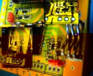
I took pics like you asked for :wink: Both low and high side drivers + dimensions of the board :wink:

Doc
 

Attachments

  • Dimension du PCB_1024x593.jpg
    Dimension du PCB_1024x593.jpg
    75.1 KB · Views: 890
  • High side Driver_934x768.jpg
    High side Driver_934x768.jpg
    147.6 KB · Views: 887
Did we talked about cooper upgrade?? :twisted:

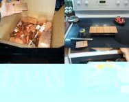
Here is what i got from my job.. some rebut from abandonned projects :mrgreen:

Usually i love to be like their trashcan!!

I'll take 3 of these block and solder them together to produce the right lenght and will cut the right dimensions.

Miraculously.. the thickness is just perfect!!

Doc
 
Doctorbass said:
Question:
I wonder if sanding the fet back and the cooper bar is better for surface conductivity than a miror style polish?
Doc
Nope. :)
You want the smoothest and flattest surface you can get. Sanding either digs channels in the metal and/or pushes up the metal to form ridges. Both of these reduce the metal to metal contact, which is what you need. Ideally, after removing a MOSFET from its mounting, you want to see MUCH less than a 1mil coating of thermal transfer compound (very even) between the two surfaces. Essentially, all you want to do is fill in the micro air spaces that form the low spots between the two metal surfaces.

And I can't overstress the importance of the surface being both smooth and flat. You can have a beautiful mirror surface finish, but if the surface is bowed even 1mil up or down over the width of the metal bar (or whatever), that forms an air space between the two metals. Yes, it gets filled in with thermal transfer compound. But, as mentioned earlier, the compound's thermal conductivity is MUCH worse than copper's.

Do not sand or try to smooth a surface with your fingers pressing down the sandpaper. Use a another very flat block of metal to hold the sandpaper. NOT a block with a from-the-mill surface!! These are not flat as you can tell by rubbing two together and seeing just the outside edges get abraded/rubbed. A machined surface may not be smooth, but it is typically very flat and is often the best for holding the sandpaper.
 
Ok thanks Camlight! i'll polish copper!! :wink:

I have something at my job to polish up to 1um suspension powder!!that will be like the hubble mirror! but flat..

Here is some copper waste from my job's mechanical engeneering department that i got for free and began to adapt for my needs!!

next step: cut and polish to the new enhenced dimensions!... and flatness!! (soon)

Doc
 

Attachments

  • compil 1_960x768.jpg
    compil 1_960x768.jpg
    104.2 KB · Views: 830
  • compil 2.JPG
    265 KB · Views: 1,245
  • compil 3.JPG
    261.6 KB · Views: 1,257
wrobinson0413 said:
Thanks Doc for the pictures of the high side driver. I would not have guess that they would go discrete on the high side since it is always hard to get a good level shifter circuit that can switch at a decent speed for both turn on and turn off conditions without consuming lots of current or using lots of components. Do you know how high in voltage that anyone has run this controller at? It would be interesting to know because now that you know that they created the level shifter and gate buffer from discrete components, they may not be rated for too high of a voltage. You may want to ask the manufacturer what voltage the transistors are rated for, and how high of a bus voltage they tested their circuit to. If you know people that are runing these controllers at high voltage, then it is probably of no concern.


I sau a post about the infineon board (the 12 fets board version that is able to take 90V according to the upgraded voltage regulator. (see Infineon controller for dummy)

I will ask Keywin tomorrow for the specs on these driver transistors.

Doc
 
Doctorbass said:
Here is some copper waste from my job's mechanical engeneering department that i got for free and began to adapt for my needs!!

Doc
I am soooo jealous that you have that gorgeous box of copper to play with. :p
 
Doctorbass said:
I sau a post about the infineon board (the 12 fets board version that is able to take 90V according to the upgraded voltage regulator. (see Infineon controller for dummy)

I will ask Keywin tomorrow for the specs on these driver transistors.

Doc
I checked the SMD codes and found the following:

Low side driver Q4B and Q5B = BZV49C11 or BZX84-C11 = 11V, 5% zener diode
Low side driver Q3B = BZX84-C12 = 12V, 5% zener diode

High side driver Q2A and the one above R0A = BZX84-C12 = 12V, 5% zener diode
I can't read the writing on Q1A.

Doc, are you able to read the code on device Q1A?
 
CamLight said:
Doctorbass said:
I sau a post about the infineon board (the 12 fets board version that is able to take 90V according to the upgraded voltage regulator. (see Infineon controller for dummy)

I will ask Keywin tomorrow for the specs on these driver transistors.

Doc
I checked the SMD codes and found the following:

Low side driver Q4B and Q5B = BZV49C11 or BZX84-C11 = 11V, 5% zener diode
Low side driver Q3B = BZX84-C12 = 12V, 5% zener diode

High side driver Q2A and the one above R0A = BZX84-C12 = 12V, 5% zener diode
I can't read the writing on Q1A.

Doc, are you able to read the code on device Q1A?

Yes it's G1

Doc
 
CamLight said:
Doctorbass said:
Yes it's G1

Doc

Thanks Doc,
High side driver Q1A = MMBT5551 NPN transistor, 160Vce or BFS20, NPN transistor, 20Vce

I suspect that it's the MMBT5551. :mrgreen:

Great.. that sound's like pretty similar to my crystalyte controller spares parts 2N5551 in the to-92!

160VVce.. how do you think it get with 100V on the controller?.. any overshoot spike possible on it?

Doc
 
Doctorbass said:
CamLight said:
Doctorbass said:
Yes it's G1

Doc

Thanks Doc,
High side driver Q1A = MMBT5551 NPN transistor, 160Vce or BFS20, NPN transistor, 20Vce

I suspect that it's the MMBT5551. :mrgreen:

Great.. that sound's like pretty similar to my crystalyte controller spares parts 2N5551 in the to-92!

160VVce.. how do you think it get with 100V on the controller?.. any overshoot spike possible on it?

Doc

I guess you'll have to take a scope and probe a few area to see how high voltage can spike when runing it at no load or with some load (rear brake).

Robin
 
Doctorbass said:
160VVce.. how do you think it get with 100V on the controller?.. any overshoot spike possible on it?

Doc
It's certainly possible. I'm with Robin, use a fast scope and see what the spikes go up to.
 
CamLight said:
Doctorbass wrote:Here is some copper waste from my job's mechanical engeneering department that i got for free and began to adapt for my needs!!

Doc

I am soooo jealous that you have that gorgeous box of copper to play with. :p

Me too. :D Very nice.
 
Doc,

I figured you would have some copper bar sitting around, but I didn't think of a box like that. :shock:

Yes definitely regarding black with the controller. My Infineons always ran hot, even with full air circulation. I painted mine black to hide it better in a space with much less air circulation, and now it runs significantly cooler. I thought about the better emissivity when I was painting it, but I dismissed it thinking the radiation would be very low at these temperatures. I'll leave the number crunching to you guys who don't have to look it up, and just say that I was quite pleasantly surprised with a cooler controller, despite the more restricted ventilation.

John
 
hi
you talked about how high the controller will go voltage wise, I took a 12fet controller with a transistor voltage regulator modification up to 99v on a puma motor under no load with two psu's so the power was low but it was under no load.

who knows what you could do if you could put some power behind that.
Geoff
 
Heat loss from a controller case occurs by two mechanisms, convection and radiation. Around 75% of the case heat will be lost by convection, with the remaining 25% lost by radiation.

Convection depends on the movement of air past the controller case, either from the heat of the case itself making air near to it move, or by some form of forced ventilation. The colour of the heatsink doesn't really make much difference to the effectiveness of convection, that's mainly determined by surface area and the temperature difference between the air and the heatsink.

Radiation is dependent on the emissivity of the case as well as it's surface area. A polished alloy case has an emissivity of about 0.05, whereas a case with a thin matt black coating will have an emissivity of around 0.9. This means that the black case will radiate around 18 times more heat than a shiny silver one.

Although painting a controller black will help, it will only increase the effectiveness of the radiated heat loss element, not the convected heat loss part. A small fan will massively improve the effectiveness of convected heat loss. It doesn't need to be a big or noisy fan, anything that causes air flow over the case to speed up will make a significant difference. An airflow past the case of just 1.5m/S (about 3.5 mph) will just about double the rate of heat loss by convection.

Jeremy
 
Back
Top