JP spot welder

rio9210 said:
This is my final setup with JP SPOT WELDER REV 2.0, as is stated on PCB :)


Lenght of cable (10-25 mm) is 70 cm, as suggested by riba2233. The welder part is 20+50cm. Used two DINSE connectors (10-25 mm) with two brass tips soldered on the end of DINSE connectors (industrial solder process, not homemade - you have to find the guy that can do this for you). Heatshrink was used on cable-DINSE junction, and two brass battery connectors.
I could not get a set-up cheaper than this. Frankly speaking, I didn't get far from riba 2233's cost.

By the way, 6 nickel strips 0,15x8mm (soldered between parallel rows of 18650 batteries) carrying 5-6 A each one should be enough for a 10S6P 21 Ah battery, right ? I don`t want to bother with manually soldering copper wires if I can do the same job with the spot welder and nickel strips.


It looks fine, but I'm not sure about brass tips, please tell us how they perform :)

For that current, it should be fine!
 
riba2233 said:
rio9210 said:
This is my final setup with JP SPOT WELDER REV 2.0, as is stated on PCB :)


Lenght of cable (10-25 mm) is 70 cm, as suggested by riba2233. The welder part is 20+50cm. Used two DINSE connectors (10-25 mm) with two brass tips soldered on the end of DINSE connectors (industrial solder process, not homemade - you have to find the guy that can do this for you). Heatshrink was used on cable-DINSE junction, and two brass battery connectors.
I could not get a set-up cheaper than this. Frankly speaking, I didn't get far from riba 2233's cost.

By the way, 6 nickel strips 0,15x8mm (soldered between parallel rows of 18650 batteries) carrying 5-6 A each one should be enough for a 10S6P 21 Ah battery, right ? I don`t want to bother with manually soldering copper wires if I can do the same job with the spot welder and nickel strips.


It looks fine, but I'm not sure about brass tips, please tell us how they perform :)

For that current, it should be fine!

What are your concerns about the tips ? Have a look at the foto, they seems fine

HBzg9Zi
 
For some f..king reason the forum does`t load the images. However, here are Imgur links

http://imgur.com/HBzg9Zi

http://imgur.com/AehnW8n

http://imgur.com/zlfZVNe
 
No one said they won't work. We're all waiting, with baited breath, to see if they do. Me? I try to go with what the maker confirms will work perfectly, and not reinvent. But never mind me, I do customer service an tire of those who take their own route and then bitch when it fails. :wink:
 
riba2233 said:
I like this style:

OuLD1UGl.jpg


This is nickel in combination with silver coated copper wire, can carry all amps you want :)

riba I think I have to agree with you. This may be the cheapest or most economical way to get the pack to allow the most amps through it.

Using nickel sheets like madin88 has done in his Dn 5 thread, like the .2 mm sheet you recommended is too expensive to cover a very large battery with them, like my 240 cell battery I need to build. I would have to waste a lot of material trying to make all the connections with it because i need to cut it away from a 90mmx1000mm sheet, I can't utilize all of it without lots of waste.

One thing I was wondering about riba is in that doesn't the battery in the picture lack the support of the nickel tabs in series? There are no nickel tabs connecting them in series.

I was thinking about still connecting everything with .15mmx7mm tabs, and adding the copper wires on top of all of the tabs. Does that make better sense so that I have the support of the tabs with the series connections?
 
Hi all,

I need to use capacitors instead of a car battery for the JP welder.
Reason is that i'm going to use the JP welder on a CNC based system modified for spotwelding.
To prevent long cables (this system has 90cm X-travel and 40cm Y-travel) i'm going to mount the JP welder with welding tips on the Z-arm of this CNC machine and there's no room for a heavy battery. I was thinking of using the Zeva CD spotwelder that has 24 capacitors of each 47000uF in parallel releasing their charge over a powerMOSFet instead of the car battery but use the JP welders PCB.


Any other options ?

Thanks,

Paul
 
Someone else tried a big capacitor and it worked. Just keep the voltage below 12v or so.
Another option would be high rate Lipo batteries or A123 cells. Much lighter.
 
Offroader said:
riba I think I have to agree with you. This may be the cheapest or most economical way to get the pack to allow the most amps through it.

Using nickel sheets like madin88 has done in his Dn 5 thread, like the .2 mm sheet you recommended is too expensive to cover a very large battery with them, like my 240 cell battery I need to build. I would have to waste a lot of material trying to make all the connections with it because i need to cut it away from a 90mmx1000mm sheet, I can't utilize all of it without lots of waste.

One thing I was wondering about riba is in that doesn't the battery in the picture lack the support of the nickel tabs in series? There are no nickel tabs connecting them in series.

I was thinking about still connecting everything with .15mmx7mm tabs, and adding the copper wires on top of all of the tabs. Does that make better sense so that I have the support of the tabs with the series connections?

There's no need to connect them in series with nickel, this is more than enough, and it makes servicing easier :)

rio9210 said:
What are your concerns about the tips ? Have a look at the foto, they seems fine

HBzg9Zi


Well brass has higher resistance, so it could stick. But who knows, you should try it, I really want to see the results! :)

prensel said:
Hi all,

I need to use capacitors instead of a car battery for the JP welder.
Reason is that i'm going to use the JP welder on a CNC based system modified for spotwelding.
To prevent long cables (this system has 90cm X-travel and 40cm Y-travel) i'm going to mount the JP welder with welding tips on the Z-arm of this CNC machine and there's no room for a heavy battery. I was thinking of using the Zeva CD spotwelder that has 24 capacitors of each 47000uF in parallel releasing their charge over a powerMOSFet instead of the car battery but use the JP welders PCB.


Any other options ?

Thanks,

Paul

Some people done it already, check few pages back. But you would need to experiment. Also, like fechter said, you could use like 2S 10 Ah of some extra strong lipo cells, it should be even smaller than capacitors.
 
Offroader said:
How do I figure out the best way to connect the cells with nickel tabs for best series contact? In a 20s12P configuration.

I'm going to build a pack with 240 cells laid out like shown in the picture.

Is there a computer software that can line up the cells in the most efficient way?

file.php

Hey Offroader, here is the Visio file I used to create that drawing. DROPBOX LINK TO BATTERY DRAWING VISIO FILE

Go to the second tab called "q76 - 20s12p -240 Cells" to find that image.
 
Hello all,
Just received my kit today. A++ feedback on the DIY kit.
Clear instructions, easy operation, great welds !
I made fast tests with badly connected 3S 2250mAh old heli lipo... it worked great.
I'll work to do clear connections and add optional parallel lipo setup for more current and lower weld time.

No regrets. Great price.
 
seb13 said:
Hello all,
Just received my kit today. A++ feedback on the DIY kit.
Clear instructions, easy operation, great welds !
I made fast tests with badly connected 3S 2250mAh old heli lipo... it worked great.
I'll work to do clear connections and add optional parallel lipo setup for more current and lower weld time.

No regrets. Great price.


That sounds great! :)
Thanks :)
 
Riba, I have drawn my plans for a 20s12P 3KW (120 battery amp max) pack for my Qulbix Q76R frame using your copper wires for series connections.

Because of having 12 cells in parallel I don't find it necessary to solder 12 different wires to make the series connection. So I decided on using 3 wires to connect each series.

In the diagram the Red lines are series connections made on one side and the black lines are on the other side. I will make the series connections on exactly the same areas on both sides.

Because I plan on using 120 max battery amps (Peak), most likely lower continuous, do you see any issues with using 3 copper wires to connect each parallel groups like I have drawn?

I will use 12 gauge AWG wire (unless you think I should use smaller) for making the series connection, so 3 separate 12 gauge wires I assume will be more than suffiecient for passing 120 Peak amps.

The gray lines will be .15x7mm copper plates. I will not double up anyplace unless you see issue.

Thank you for taking the time to look at the chart and let me know if you see any problem with the way I have designed the pack. If anyone else sees any issues feel free to comment.

*EDIT: Picture updated below
 
Offroader, it looks ok to me, but I think it's better to have a shorter path to the series wires if possible, and to keep the links before each wire similar for all cells.
If you look at the cell in the corner of each parallel group, it has to go through the nickel on 2 cells before it reaches the wires, were as other cells only have 1 or no nickel connections to go through.
This will create an imbalance in your back over time and drain the cells closest to the wires faster.
It's not a huge issue, and TBH probably won't cause you any problems, but something to be aware of with your design.

Cheers
 
I am liking the parallel group arrangement but agree with CD that the series connection could be improved upon. I know its not easy to get the series connections optimised and what you have drawn certainly will work. I will have a bit of play with the series connection layout and see if I can get it any better. :)

edit; I have an older version of Visio, could you please save a copy in Visio 2010.
 
Yes you guys are right! I actually also realized that I could make it better.

I am going to add .2mm copper sheet to the center of each parallel group.

This will help the higher amp area of the center of the parallel groups which has the series connections to it and also the parallel cells on the outside flowing through it also.

The series connections also can be a bit more efficient.

I'm going back to the drawing board!
 
Some people done it already, check few pages back. But you would need to experiment. Also, like fechter said, you could use like 2S 10 Ah of some extra strong lipo cells, it should be even smaller than capacitors.

I have design here of a spot welder made of 24 caps 47000uF/16V.
They are grouped in 3 and triggered by two IRFB7430 FETs in parallel.
All 8 groups are then connected in parallel and the MOSFETS are all triggered in parallel by just a 12V signal.
Theres no timer involved just one shot until the caps are empty.

Now looking at the Riba design it looks very similar.
So in my opinion i could just connect 24 caps of 47000uF/16V all in parallel and use these as direct replacement of the battery.
Then connect a lab supply set to 12V as charger on the caps.

Are maybe use the other welder (bigger and more MOSFETS) and 'abuse' the Riba welder for just the MOSFET timer/triggering system ?
 
OK, I took it back to the drawing board and made this much better I think.

Kepler, forgot to mention, thanks for you sharing your drawing some posts back, it was very helpful.

What I have added here is where you see the filled in gray area on each parallel group, I will place here a thick piece of .2mm copper plate. This will connect 6 cells with a .2mm x 25mm x 45mm plate. This thicker and more surface area plate is centered to allow a much better flow where the amps will be at their highest.

(If anyone is interested in seeing the larger plates being used it was first suggested by madin88 in this thread)
https://endless-sphere.com/forums/viewtopic.php?f=14&t=67903

The outside cells will still be connected with a .15x7mm plate, but these will see a low amp draw.

I made the series connections connect at three points on this thick center plate which is right between two cells for each connection. Spreading out the copper wire connections will allow the current to more quickly flow into the copper wires which are much more efficient at moving the current than the plates.

I don't see any better way to make the series connections any better as the current has to flow to the center of each parallel group. I don't see any better way to make these series connections shorter. Unless you think I should maybe use a single larger wire and center it? Instead of using three separate wires?

If anyone can see a better way to do this I would like to hear from you.

Thank you, this battery configuration was made using all your guys suggestions on this forum.

The black and red lines in the picture are series connections with the black being on one side and the red being on the opposite side.

EDIT: Picture removed for an updated photo below.
 
Offroader said:
OK, I took it back to the drawing board and made this much better I think.

Kepler, forgot to mention, thanks for you sharing your drawing some posts back, it was very helpful.

What I have added here is where you see the filled in gray area on each parallel group, I will place here a thick piece of .2mm copper plate. This will connect 6 cells with a .2mm x 25mm x 45mm plate. This thicker and more surface area plate is centered to allow a much better flow where the amps will be at their highest.

(If anyone is interested in seeing the larger plates being used it was first suggested by madin88 in this thread)
https://endless-sphere.com/forums/viewtopic.php?f=14&t=67903

The outside cells will still be connected with a .15x7mm plate, but these will see a low amp draw.

I made the series connections connect at three points on this thick center plate which is right between two cells for each connection. Spreading out the copper wire connections will allow the current to more quickly flow into the copper wires which are much more efficient at moving the current than the plates.

I don't see any better way to make the series connections any better as the current has to flow to the center of each parallel group. I don't see any better way to make these series connections shorter. Unless you think I should maybe use a single larger wire and center it? Instead of using three separate wires?

If anyone can see a better way to do this I would like to hear from you.

Thank you.

The black and red lines in the picture are series connections with the black being on one side and the red being on the opposite side.

It looks fine, square area is enough for 120 A, but you'll have to be extremely careful while assembling the pack.


prensel said:
Some people done it already, check few pages back. But you would need to experiment. Also, like fechter said, you could use like 2S 10 Ah of some extra strong lipo cells, it should be even smaller than capacitors.

I have design here of a spot welder made of 24 caps 47000uF/16V.
They are grouped in 3 and triggered by two IRFB7430 FETs in parallel.
All 8 groups are then connected in parallel and the MOSFETS are all triggered in parallel by just a 12V signal.
Theres no timer involved just one shot until the caps are empty.

Now looking at the Riba design it looks very similar.
So in my opinion i could just connect 24 caps of 47000uF/16V all in parallel and use these as direct replacement of the battery.
Then connect a lab supply set to 12V as charger on the caps.

Are maybe use the other welder (bigger and more MOSFETS) and 'abuse' the Riba welder for just the MOSFET timer/triggering system ?


I can't tell for sure if it will work, I don't have any experience with it, but you should try and report the results. It might, because it's bit over 1F and if caps are high quality, low impedance, they should be enough.
 
One thing to keep in mind when arranging cells for a pack is to try and keep the path resistances for all the cells as equal as possible. If you have a parallel group connected by wires, the cells closest to the wire connections will have a lower resistance path and therefore will see a higher load during discharge. If every single cell has its own series connection, the current distribution will be fairly even. If the series wires are placed half way between a pair of cells, the pair will be even. Balancing the load is really only an issue at very high discharge rates, but if done carelessly could make some cells overheat or fail sooner than others.
 
fechter said:
One thing to keep in mind when arranging cells for a pack is to try and keep the path resistances for all the cells as equal as possible. If you have a parallel group connected by wires, the cells closest to the wire connections will have a lower resistance path and therefore will see a higher load during discharge. If every single cell has its own series connection, the current distribution will be fairly even. If the series wires are placed half way between a pair of cells, the pair will be even. Balancing the load is really only an issue at very high discharge rates, but if done carelessly could make some cells overheat or fail sooner than others.

Fechter, do you think I will have any issues with my parallel groups. I see what you mean that the cells closest to the where I connected the wires could have more load.

In my picture you can see only 6 pink cells are right next to the three 12AWG series wires. The other 6 pink cells are on the outside and spaced a little further away and have to pass through .15mmx7mm nickel strip.

Each cell could see a max current draw of 10 amps,.

Do you think I should solder a small 24AWG wire between the outside cells and connect them to the main series wires in the center? I drew another picture showing this. I believe this would help more evenly distribute the load between the parallel cells. Or is it totally not necessary?

I drew small green wires showing where I can run copper wire to the center. It shouldn't be all that difficult to solder it in.


10A per cell is quite a bit for those thin nickel strips. Adding wires as shown would help, but would sure be a lot of work.

There are many ways you can arrange the connections. The 'brute force' approach is to use very heavy interconnections such that the voltage drop is negligible. Another way is to arrange the connections such that each cell 'sees' the same total resistance to the series connection (a picture would be good here).

Ideally, each cell would have its own series connection to the next block, and the parallel connection can be small, since it doesn't carry much current. It would be hard with that pack arrangement though. Easier to implement in a nice rectangular pack.

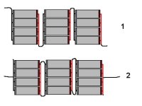
OK, I found an old diagram that shows the basic idea:

Series Connection Layout.jpg

In figure 1, the resistance (path length) of the interconnections for each cell will be equal, so current distribution between cells will be equal.
In figure 2, the ones on the ends will be close to equal, but the one in the middle will be concentrated toward the outside cells (not as good). In both of these, the interconnections carry both the series and parallel currents, so more copper is needed compared to each cell having its own series connection.

Keep in mind that at lower currents, all of this is moot as the voltage drop in the interconnections will be so small it won't matter. Only at high rates will this really make a difference. Don't worry too much if your strips are hefty.
 
Back
Top