Micro Lebowski Controller - DIY 3kw

izeman said:
So my idea to set battery to 50 and phase to 150 seems like a good idea anyway? My motor has a temp probe at the windings and my CA dials down power as the temp reaches 120C.


Gesendet von iPhone mit Tapatalk Pro

Why did you choose those numbers?

I set the phase amps to the limit I want for a limit based on 3 things.
1 how much torque I want at full throttle. (do I want more if yes then turn it up)
2 the motor windings limits the phase amps will determine the current in the windings and that is why they need a temp sensor
3 controller power stage current limits. If 1 and 2 allow it to be turned up then 3 will be the limit.
 
good question. with my very old infineon controller, and with the kelly (sine and squarewave) i could climb up stairs in first gear from a standstill. with this controller now i just does NOTHING. if i get it rolling it works, but from a standstill. no.
but i need power to be able to start the bike on a hilly, rocky, steep single track. if the bike just say NAHH it's motor is useless.

i have NO IDEA how much the windings can take. how would you define the limit? based on voltage drop? heat? melting?
the motor has a temp sensor, and i use the CA's standard power limiting starting at 90° and cutting all power at 130°.

so i can now say: i want to do a 30km ride and don't want to have any power limiting. so i dial down phase current until the motor will never overheat. but it won't climb a hill with a too low phase current. it's not about shooting up the hill. it's just IMPOSSIBLE to get the bike going.

the controller itself should be capable of 150A phase. the FETs need cooling, but they need that anyway.

and that's why i chose 50/150. 50 battery means 2.5kW peak, which is the limit for the motor, and for the bike components imho. and 150 because with this value the bike almost can do what i need :)
 
Arlo1 said:
1 how much torque I want at full throttle. (do I want more if yes then turn it up)
are you sure it's for full throttle? do you mean fully opened throttle at any speed, or max torque at max speed (=full throttle)?
because ihmo max power at full speed is limited by battery current and not phase current. phase current is important for low speed/rpm.
 
izeman said:
Arlo1 said:
1 how much torque I want at full throttle. (do I want more if yes then turn it up)
are you sure it's for full throttle? do you mean fully opened throttle at any speed, or max torque at max speed (=full throttle)?
because ihmo max power at full speed is limited by battery current and not phase current. phase current is important for low speed/rpm.


Phase current is your torque at any speed. full throttle is full phase current. If you set your phase current higher then at full throttle you will have more torque.

Battery amps limit how high of rpm you can achieve full phase current.

if you set the battery amps to the same number as the phase amps and use a little field weakening you can achieve a smooth flat torque curve to top speed.
 
Arlo1 said:
Phase current is your torque at any speed. full throttle is full phase current. If you set your phase current higher then at full throttle you will have more torque.
yes. but only as long as BATTERY current goes up as high as well. if my battery current is 50A and FETs are full open at full speed, then the phase current is limited to 50A. at least is that how i heard controllers work.
 
Max motor (phase) current occurs at fairly low speeds when the back EMF is low. At some higher speed the back EMF prevents this current from being achieved, toward higher speeds (depends on motor windings). So setting the motor current max determines maximum launching and low speed torque.

Like Arlo, I don't worry about a particular ratio, I set it for how much low speed torque I want and how much motor heating I'm willing to allow. I squared R will determine heat in the motor, measure your motor's resistance (or look it up) to calculate motor heating. Choose how much motor heat you are willing to allow. Look at the wire and connectors, how much can they handle? And of course the controller FETs, how much can they handle safely when they are hot?

In the case of the Borg, where there is a big battery, controller and motor, I set the phase current limit to control how fast and how far the front wheel lifts off the ground during hard acceleration. In other cases I set it by the knee in the torque curve from saturation where the motor efficiency drops, or by the motor wiring and connector size.

The battery current limit controls total power. What can the batteries, wiring, BMS and connectors handle? What is legal? You have to choose. The battery current limit generally has no effect at very low speed, it starts to limit only when the speed rises to some point (still may be a fairly low speed), when the battery current rises this limit comes into play. So it controls mid range acceleration and power.

As the speed rises further the back EMF takes over and becomes the limiting factor, and changing either of these limits has no effect. Field Weakening then has effect at these higher speeds, and if enough FW current is dialed in then the battery current limit may come into play at high speed.
 
thanks alan. that's more or less what i learned as well and makes sense. the problem is, that at VERY low rpm (around zero) you have to have an infinite current. as soon as rpm raises your battery current will become the limiting factor.
150A @ 0 rpm = 0 W + heat.
the battery, bms, controller/fet, connectors can handle the current. the question is: how long can the motor handle that? and this can only be found out by try and error.
setting the phase current so the front wheel lifts? well. my front wheel NEVER lifts. not in first gear, with 150A and 2.500W total. power application is very smooth and there is no kick in the back.
 
izeman said:
Arlo1 said:
Phase current is your torque at any speed. full throttle is full phase current. If you set your phase current higher then at full throttle you will have more torque.
yes. but only as long as BATTERY current goes up as high as well. if my battery current is 50A and FETs are full open at full speed, then the phase current is limited to 50A. at least is that how i heard controllers work.


NOPE.

Battery amp limits how many battery amps can flow and it will limit the phase amps but not at 50amp it will limit the peaks to a calculated amount for the given back emf and the given battery voltage and internal resistance among a few other things. The numbers it limits the phase amps at will be at higher rpm and it will be different for many different scenarios.
 
izeman said:
150A @ 0 rpm = 0 W + heat.


No.


The Calculation is current thought the fets and motor x resistance to calculate the losses in the fets and motor.

150phase amps at 0 rpm will give your motor and controller the same heat as 150 phase amps at 300 rpm or 1000 rpm or any other rpm.

Phase amps are what controls the torque and the heat in the motor and almost all of the heat in the controller.
 
Arlo1 said:
izeman said:
150A @ 0 rpm = 0 W + heat.
No.
The Calculation is current thought the fets and motor x resistance to calculate the losses in the fets and motor.
150phase amps at 0 rpm will give your motor and controller the same heat as 150 phase amps at 300 rpm or 1000 rpm or any other rpm.
that's what i said :) or tried to say. heat is always the same. but the power that goes to the motor is not the same. the motor does see 150A, but it doesn't consume 2500W at zero rpm, as voltage is very low. it just produces heat. the situation start to change when the motor starts to turn. but it will need a certain rpm to really produce 2500W. at least this is what i see all the time.
 
Motor heat is motor current squared times motor resistance. Regardless of speed.

If the motor current ever goes to infinite the FETs will fail. Been there, done that. The controller that allows that is broken and that's what happens when enough mods are made to some controllers.

120 amps to a CroMotor will lift the front wheel almost off the ground on a Borg Warp frame with 23.5" diameter tires.

It sounds to me like izeman is not getting the phase current he is setting in the controller. At low speed you should get it unless there is too much resistance, or something is wrong.

It is simple ohms law. What is your motor resistance? What is your max phase current? Motor voltage is current times resistance. The ratio of battery voltage to motor voltage gives the approximate current multiplication at takeoff. On the Borg 120 amps times 100 milli ohms is about 12 volts, battery voltage is about 72 fresh off the charger, so current multiplication will be about six and therefore battery current at launch is about 20 amps to produce 120 amps of motor current.

If the FETs turn fully on (which is what full throttle wants to do), the 70 volts divided by the 100 milli ohms of resistance will flow 700 amps, not infinite, and the FETs will quickly open up, melting leads and traces. PWM controls the effective voltage presented to the motor, so if the FETs were PWMed at 50% the voltage would be about 35 and the current flow would be about 350 amps. To get the 120 amps flow the PWM needs to be on about 1/6th of the time, or 16.7%.
 
Alan B said:
It sounds to me like izeman is not getting the phase current he is setting in the controller. At low speed you should get it unless there is too much resistance, or something is wrong.
no no. i DO get full amps as soon as the bike is moving. this is not different from 100% of the bikes around there :)
i just mentioned, that i would welcome even more phase amps, but this a) is out of the controllers scope, and b) will heat the motor even quicker.
@alan: do you use a torque throttle controlled sine wave controller? or one of the "old" trapezoid ones? they gave a massive kick when starting the bike. lebowski's controller is very gentle and smooth on the throttle.
 
The Borg has a Sabvoton sinewave controller and it gives a very hard acceleration. Sinewave controllers with hall sensors can do that because they don't have to spend time figuring out where the motor is that could be used for thrust. Hall start is good for quick thrust.

The dual PhaseRunners on the Bonanza are also Hall Start FOC run. The motors there are weaker and the acceleration parameters are set longer so it doesn't have a kick at all.

The Sabvoton and PhaseRunners are torque throttle. It is excellent.

It mostly depends on the timing, the settings of filters, ramps and feedback loops. No reason a sinewave controller cannot kick hard, they are just full of control software that tends to slow things down and keep it safe and sane.

The real fundamental difference between trap and sinewave controllers is the way the field in the motor moves. Sinewave controllers rotate the field smoothly while trap controllers jump it in 60 degree chunks.

The big kick from many trap controllers is mostly due to poor control of current, it jumps very high at the start due to their software. The high current is not efficient, but it does result in some additional thrust.
 
good evening all..

Just a quick note that my lebowski ran an ASTRO motor today on the 'bench' at full noise 48V with the fan attached to the astro. it was loud, but not too loud... It seemed to run quite well.

I really need to get it inside a box case so I can test it properly under load.

That's it for now.
Later
Andy
 
Animalector said:
Yeah it's old software. I probably need to send the board over to Lebowski to reprogram. Probably cost less to have him send me another chip. Or two.
yep. order one or two. the new upgrade feature is AWESOME! much better than sending it forth and back around the world.
i up/downgraded now at least 20 times and it worked flawlessly all the time. very well thought out.
 
ok so.... I was looking ages ago at this SMT FET package, which looks excellent on paper. https://www.fairchildsemi.com/datasheets/FD/FDBL0240N100.pdf, well I thought I could do better with my layout to make it easier to build, and solder.

so.. Here is a single phase, Phase B goes above this one and so on... The high current path is on the left, where the 10GA wires for Battery + and - will come in and is soldered the full lentgh of the board, this shall be exposed / tinned copper, 5mm width minimum
The -Bat branches for each phase on the bottom of the board, and this can be beefed up with copper wire. The +Bat branches out on the top of the board and can also be beefed up with copper wire..

Now the tricky bit.. The slot, is for a 1mm copper sheet bent into a Z shape to bridge the top layer +VBat to the bottom layer +VBat right into the FETs.

I think this is about as good as I can get it... At least now I have done away with the posts, and managed to get it all on a single plane. I think capacitor placement is pretty good, it's very local to the FETs and the current won't have far to travel to get to the FETs as required.
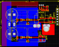
single_phase (Custom).PNG

So thoughts???

The limitation of this layout is the current sensors maxing out at 200A bi directional. But that's still pretty good for a layout that's potentially going to be 60mm wide and around 160mm long...
 
Instead of a slot with the copper sheet, can't you make lots of little plated through holes and fill those with solder, a bit like packaged plate heat sinks for the small LTC dcdc converters ? If you go that route you can extend the red trace further underneath the big caps and have it overlap the gnd trace more, maybe even have all the little solder filled through holes there where you have the positive cap connections.
 
yeah I could do that but I was worried about 200 Phase Amps through vias filled with solder... and thought copper sheet would be better...

Yep filling under the Caps where the +VBat is connected is easy and I'l do it. This section won't be exposed though, it'll be under the solder mask, only the red hashed section is intended to be exposed. to allow plating with copper wire / or perhaps laser cut sheet...?

good suggestions thanks Bas...
 
have you thought about heat-sinking (active or passive) and how that will be connected to your PCB ?

I would recommend for PCB design in altium to use 3Dcontinental or similar website to find 3D step files (for free) for your components and then use them in your library which is very easy and simple , it also helps you in drawing the 2D footprint and not making mistakes , The final 3D visualization is great and could save some iterations of the design , and it looks awesome ... just my 2 cents ....
 
Yeah. My version of altium is really old... I really should use something newer...

this board will go face down onto an aluminium block or case with thermal paste on the body of the fets. Nothing fancy there.
 
It's a shame I can't really make use of this space, but I think inductive noise will be too much for any sort of drivers placed here.. oh well.. I'll keep it clear, I thought about putting the driver IC in this area, but getting the digital signals to it would be inviting problems I think. If it was possible I could get rid of my driver PCB and have only a two layer board. perhaps I can increase width and find a wider case. then have the driver on the right-side of the circuit board.


BTW, I added 60+ vias instead of the Z-Bent copper.. it looks nice, but I don't know ... it's only 3A per via, which is actually ok for a 1mm hole via... I'll add a photo when I get home.

Andy
 
Back
Top