Mid monster/Hub monster powered cruiser in mind, seek advice

Bluefang,

I know you understand the benerfits of higher voltage. Hell you were the first to do it with our motors. Tell your brother I'll send him a nice present when he pulls it off.


UPDATE of MidMonsters specs:

It turns out the out of balance condition I still had what increasing no-load current by 10%. I balanced one today and the no-load current at about 1650rpm was only 1.8A .

FWIW, I chucked a HubMonster in the vise with no wheel and the Kv was slightly over 18rpm/v, and at 107.1V the no-load current at 1965rpm was 3.41A . We backed the throttle to 50%, and at 1000rpm the no-load current was 1.52A. It makes sense that HubMonster draws a bit more, since it has more steel and more torque for a given input than MidMonster.

Phase to phase resistance to come, which when combined with Kv and no-load amps can really tell you a tremendous amount about a motor. I'll get with some of the true experts and post a topic to explain in layman's terms the interactions, along with my ideas of how to look at simple motor specs (if we're lucky enough to get any at all), that give use a good way to compare motors and what to expect.
 
Ok so I can start with the "off the box" sealed motor and only if improvements are needed should I unseal it, given that it is not much of a threat as it spins too fast to get damaging objects to enter it. Thanks for your input guys :wink: and thanks for the build link and sprocket trick Bluefang!

I look forward to the thread with hubs comparisons, right now I'd summarize my understanding of internal hubs as "more phases equals smoother and broader range of torque, more strands equals more magnets thus more conducting material hence bigger power capacity for the same size".
If I try to base on the hubmonster no load test, you should draw an even lesser current on the mid monster when backing off throttle right? Less heat and less stress on it between accelerations.

EfrenBatt :arrow: Welcome to my thread, sorry I'm not sure to understand what you were trying to say. Was it an "analogy" to refer to the variety of parts available to riders? No offense here, my english is not flawless and I just make sure you didn't post on the wrong topic :p (I would not say that it is your first post and it looks like a spam, should I?)
 
My mention of strand count was for comparison with another motor with a known number of same size wire strands wrapped around the teeth, so more strands means thicker copper wound on the motor and higher current handling.

The primary advantages of these 6 phase motors are:
1. The startup under load is smoother and more quiet, so sine wave controllers aren't really needed. You might be able to hear something if listening closely, but nothing like a rattletrap 3 phase hubbie on takeoff.
2. Running 2 controllers makes it much cheaper to get to high power.
3. You can still get home if one controller fails, though you would need to disconnect the failed one, and no climbing steep hills on one controller.

Other things said about higher phase count motors is just noise. Stator steel (it's width, diameter, and quality) and magnets are what establishes a motor's torque limits, and winding MidMonster as a 3 phase or 6 phase won't change torque.

No load current is primarily from iron losses and is related to rpm, and would decrease with rpm. Copper losses from resistance in the windings is by far the primarily source of heat in the motor, and it varies with current...actually the square of current.

Out of the box you will need to cut off the rim. I'm going to do another of mine and get pics and maybe video of that process. I also want to try to cut channels in the thick AL shell for more surface area to make it reject heat better, something it sounded like you have better connections to do the same to your motor.
 
Sure I can cut the rim myself, by "out of the box" I was referring to the sealed state you were talking about. I'll wait for your results to see how much AL can be removed before trying anything else than cutting the rim though, better not waste a fine housing by lack of knowledge.

Smoothness is a need for my build, to cruise with madame I'd rather not scare her at take off even at low speed she's cautious of 2 wheels machines. I'll try posting some proper schemes for the build this week; hard to get a pause and to properly make things recently. I might also post some parts options, please tell me what you think of it (reliability wise).

I'm trying to figure the best compromise on instrumentation, Sabvotons controllers offer Android link for getting all data on the smartphone yet a small secondary gauge for battery level or speed might be easier to read in full sunlight.

Do you know of a noisy and compact horn that easily mounts on bikes? I think the "pwet pwet" thing is more fun to look at than able to produce real noise in case of emergency .

Edit : How funny is that watting rank on the side of the window haha, just upgraded from watch accus to a rc car accu :lol:
 
I measured phase-to-phase resistance for MidMonster and HubMonster today, and the combined for both sets of phases are .045ohms and .016ohms respectively. I run my HubMonster at battery/phase current limits of 125A/190A per controller. At 250A combined phase current Hubmonster would then create 500W of heat in each half of the motor for 1000W total. MidMonster will make the same heat at 150A continuous combined from both controllers. For comparison my 3 phase 2 turn hubbies of typical construction (51 slots 46 magnets) with a Kv of 16rpm/v have a phase-to-phase resistance of .0537, so it's reasonable to expect 3-4 times higher phase-to-phase resistance. No wonder people have such heat problems at the crazy high currents they claim to run. I think I'll start referring to them as "hubheaters" instead of hubmotors. :lol:

My HubMonster definitely requires ventilated cooling at 111V nominal, which wasn't absolutely necessary when I ran 74V, but that is due to a combination of my steep gearing (170kph+ top speed) and big load (200kg including my common backpack loads). When I ran it sealed at 74V nominal my top speed was 107kph, so about the speed you want.

What all this tells me is that with your desire to keep the motor sealed, I think good current limits for MidMonster are 70-80A battery side and 105A-120A phase per controller. Despite your lighter load I still feel strongly that it's best for you to go with higher voltage 111-118V nominal (30s-32s of 3.7V nominal cells). The reason is that increasing voltage costs nothing in terms of heat for a given current, but gearing it lower has tremendous heat and therefore efficiency advantages. Those conservative current limits gives peak power input on tap of 17-18kw at good overall efficiency, and while you will very likely find that too much, you can simply turn it down by decreasing current for even less heat production and greater overall efficiency.

My goal for you is to be able to ride worry-free however you like, and be able to dial up performance as high as you want with no additional investment required. That way you are covered even with wife aboard for long trips in hilly terrain when she ends up loving it too. I understand that you want only silky smooth acceleration with her aboard, but slower acceleration doesn't stop from incurring extra heat pushing additional load. The controllers I'm testing will give you 2 separately tunable throttle response curves at the flip of a switch, so performance riding or easy cruising won't require any changes in controller settings, just a flip of the switch.

An unstressed system is the route to absolute reliability, but it can still deliver staggering performance at high efficiency.
 
Sorry about my tendency for too much detail. Now that we have phase-to-phase resistance, I'll let the numbers talk and compare 74V and 111V nominal at peak power. Let's look at 75A input per controller, 150A total.

74V x 150A = 11.1kw peak input
150A x 150A x .045ohms = 1,012W heat in the copper
add less than 100W of iron losses total heat of 1,100W
max power possible at this setting is 10,000W

Look at happens if we do what most on the forum do get more power and torque and increase current to each controller by 50%.
225A x 74V = 16,650W input and assuming we're not yet into saturation torque is 50% more too, but look at heat.
225A x 225A x .045ohms = 2,278W in the copper plus iron losses that stay the same and we get 2,366W of total heat
max power is then about 14,300W

Now let's get to higher power with an increase in voltage and reduce the gearing for the same 50% increase in torque we got by increasing current.
111V x 150A = 16.65kw peak input
copper heat is the same since current is the same, so 1,012W
assume iron losses increase by 50% due to higher rpm so total heat is about 1150W.
max power ends up 15,500W, so we get an extra 1200W of power instead of heat.

Let's say you went with the high voltage but you decide that power is excessive and/or the stock motor is getting a bit hot but you're not ready for cooling mods, so you decide to cut the current back to 60A per controller.
111V x 120A = 13,320W peak input
copper heat is now 120A x 120A x .045ohms = 648W plus iron losses of 138W for 786W total heat.
That gives us max power out of 12.5kw without heat stress.

Be careful in focusing too much on the power out number, because that's at only a single theoretical point where the gearing is ideal and the load is the lightest but the motor is still able to draw max current. The number to look at is heat, which can only change with current. With decent fresh air flow over the motor, it should be able dissipate that little heat continuously making heat a non-issue.

Everyone, and I'm as guilty as the rest, have been going about obtaining high power in a backward way. We go about pushing high current at the motor like it's something to brag about, with no regard to copper resistance, and then we go about trying to get rid of all the extra heat we create. Phase-to-phase resistance for our motors is probably the single most important spec of our motors, because it's the best guide in determining the current level we can run, yet it's never quoted. I did a google search of ES and found it only for one little geared motor.
 
Don't be sorry your like a teacher and I think that's what most of guys here including myself need !

Thank you for the numbers I'll follow this route for my build. Are the controllers in my initial post ok for the high voltage you recommend or should I search for another model ? I recall 72-100v was what it was rated, maybe the manufacturer underrate them for warranty reasons but hey I don't need to stick to warranty for a self built EV. I'm still thinking of sealed state right now because we get a lot of humidity in the air since September. Might change mind after using the bike for a while !

I hesitate to get a whole 250cc Yamaha to get strong fork and rear arms with strong brakes from the get go, plus I could take other things like the foot-stand etc from it or just check for separate parts since once the bike is completed I won't need the rest of the Yamaha. Could get a full one for 200-250€ today.
 
Vanarian said:
Don't be sorry your like a teacher and I think that's what most of guys here including myself need !

Thanks for the affirmation that at least one person reads it, so the time isn't wasted. A lot of people though, especially the younger generation, see a long post and their eyes glaze over and they skip it.

Vanarian said:
Thank you for the numbers I'll follow this route for my build. Are the controllers in my initial post ok for the high voltage you recommend or should I search for another model ? I recall 72-100v was what it was rated, maybe the manufacturer underrate them for warranty reasons but hey I don't need to stick to warranty for a self built EV. I'm still thinking of sealed state right now because we get a lot of humidity in the air since September. Might change mind after using the bike for a while !

That's not high enough voltage for what I'm talking about, and the one place they don't underrate the controllers with 100V components is voltage. If you bear with me 2-3 weeks, I'll have some solid answers for you that are more economical than the stuff you're looking at. Worst case I can let go of a pair of my Zombiess custom 18fet high voltage controllers, but what you really need is something with the dual settings for throttle and other nice features of the controllers I'm testing.

Vanarian said:
I hesitate to get a whole 250cc Yamaha to get strong fork and rear arms with strong brakes from the get go, plus I could take other things like the foot-stand etc from it or just check for separate parts since once the bike is completed I won't need the rest of the Yamaha. Could get a full one for 200-250€ today.

That kind of price for piece of mind is hard to ignore. Here used moto's get fixed and put back into service, which drives used prices sky high. Are those moto swingarms heat treated or can you modify them readily? Also, moto stuff adds significant weight, because it has to be built for any user, and you can save weight by building for your specific needs and still be plenty strong enough. A moped as a donor might be a good consideration, since they're more readily available there, giving you lighter than moto rims, but still be able to run quality tires. Something to consider is that you'll have regen braking to pick up a large part of the braking load, so maybe something like Zombiess double disc forks will deliver everything you need with more tuning options than common moto forks at a significant weight savings.
 
Copper losses increase with the square of current. This should be a sobering concept to any DIY ebiker.

For example let's say you're running 60V with 50A max current. Let's assume no-load current is 2.5A at that voltage, and since current is negligible we'll ignore the copper loss component, so the 150W (60V x 2.5a) is the iron losses. Let's further assume that your setup is reasonably good, so at peak power the motor is at 75% efficiency (power out is 2250W), and peak power occurs at 2/3rds of no load rpm, so iron losses are only 100W at peak power. That means at peak power the heat from copper resistance is 650W plus 100W from the iron, so 750W of heat, a manageable amount but near the maximum continuous heat dissipation of most stock sealed hubmotors.

First, let's double the power input by increasing max current to 100A. The copper loss will increase by 2 squared, or 4 times, so copper loss at your new peak power goes to 2600W, and because only torque increased, the iron losses stay at 100W. Now you have 2700W of heat for 6000W input, so only 55% efficiency and you now have 3300W of power output, so you increased power input by 3000W for only 1050W more output. :cry:

Now, let's double the original power input by doubling the voltage to 120V instead. We'll also reduce the gearing by half so wheel rpm is the same. Copper loss stays the same because we haven't increased current, and iron losses double due to double the rpm, so they're now 200w. Add the 650W of copper loss for 850W total, so we're still inputting 6000W, but getting 5150W power out for 86% efficiency due to the less stressed motor with lower gearing. It's the same torque at the wheel with drastically different results.

I've been following a few other threads with lively debates about motor science amongst the formally trained and highly experienced practitioners. All above my pay grade but even I was wondering why heat was not being discussed much. My simple understanding was more amps means more heat. To achieve a specific power output it was nearly always just V*A=P(watts). Hardly any consideration about heat means more lost energy and less efficiency.

The basic math described above I get as it supports my thinking. I'm still not clear about heat dissipation and its effect on these performance characteristics. At any given watt and amp combination, some amount of heat is generated and that gets dissipated in various ways. Other than keeping the motor cooler so it does not melt wires or glue with magnets flying, are there other reasons to go to extra efforts to dissipate the heat?

If it is just to keep the motor cool enough to not fail, this seems yet another reason to use more volts and less amps to achieve a given power. With variable gearing (i.e. mid drive with two sprockets) and wheel size one can tune in the maximum performance.
 
When motor get heated eventually wires get heated. And soon it is all heated, even controller and fets. And more heat means more resistance and even more losses. In which I assume controller will increase current to try to keep up the power. It was explained to me in a lay mans term where the wires are like a water hose, with the nozzle restricted you must increase water pressure to remain flow. The same with wires, fets etc. The more they heat up the harder the controller must push increased current to the motor. Which will then add even more heat.....

And at some point if heat is not removed properly there will be a melt down. For magnets and hall sensors those can die as low as 120 degrees C. Little more heat and most magnets will be de-magnetized or even the adhesive holding magnets in place will melt.

I guess worst case would be to try to go slow up a steep hill with little cooling from the speedy air, that would be a case where you would like to have water cooling, circulating pump and a radiator. So to be blunt the more heat you can remove the more power you can take out of the motor without fearing breakdown.
 
Are you saying the exact same motor under the exact same load outputs more power (watts) in cooler ambient temperatures? So a motor outputting 1000 watts at x degrees will output 1000+ when running at some temperature less than x?

that doesn't seem right; otherwise, all motor data sheets would need to state ambient temperature when running tests and they don't do that or I have overlooked that spec.
 
windtrader said:
Copper losses increase with the square of current. This should be a sobering concept to any DIY ebiker.

For example let's say you're running 60V with 50A max current. Let's assume no-load current is 2.5A at that voltage, and since current is negligible we'll ignore the copper loss component, so the 150W (60V x 2.5a) is the iron losses. Let's further assume that your setup is reasonably good, so at peak power the motor is at 75% efficiency (power out is 2250W), and peak power occurs at 2/3rds of no load rpm, so iron losses are only 100W at peak power. That means at peak power the heat from copper resistance is 650W plus 100W from the iron, so 750W of heat, a manageable amount but near the maximum continuous heat dissipation of most stock sealed hubmotors.

First, let's double the power input by increasing max current to 100A. The copper loss will increase by 2 squared, or 4 times, so copper loss at your new peak power goes to 2600W, and because only torque increased, the iron losses stay at 100W. Now you have 2700W of heat for 6000W input, so only 55% efficiency and you now have 3300W of power output, so you increased power input by 3000W for only 1050W more output. :cry:

Now, let's double the original power input by doubling the voltage to 120V instead. We'll also reduce the gearing by half so wheel rpm is the same. Copper loss stays the same because we haven't increased current, and iron losses double due to double the rpm, so they're now 200w. Add the 650W of copper loss for 850W total, so we're still inputting 6000W, but getting 5150W power out for 86% efficiency due to the less stressed motor with lower gearing. It's the same torque at the wheel with drastically different results.

I've been following a few other threads with lively debates about motor science amongst the formally trained and highly experienced practitioners. All above my pay grade but even I was wondering why heat was not being discussed much. My simple understanding was more amps means more heat. To achieve a specific power output it was nearly always just V*A=P(watts). Hardly any consideration about heat means more lost energy and less efficiency.

The basic math described above I get as it supports my thinking. I'm still not clear about heat dissipation and its effect on these performance characteristics. At any given watt and amp combination, some amount of heat is generated and that gets dissipated in various ways. Other than keeping the motor cooler so it does not melt wires or glue with magnets flying, are there other reasons to go to extra efforts to dissipate the heat?

If it is just to keep the motor cool enough to not fail, this seems yet another reason to use more volts and less amps to achieve a given power. With variable gearing (i.e. mid drive with two sprockets) and wheel size one can tune in the maximum performance.

If been waiting for someone to say, "John the stuff in this thread seems contrary to what you've been saying in the other thread, where you say it makes no difference in how you get the the same power with different windings as long as the proportions are correct in how your vary current and voltage." You didn't say that and you're 100% correct in this case, because it's a mid-drive and you come out way ahead running the same power with the same motor by increasing voltage and decreasing current, and then gearing lower for the same wheel rpm which also regains the torque lost by decreasing current. This is true as long as the motor can still handle the higher rpms of the higher voltage. In the case of MidMonster, and HubMonster too for that matter, they are built with top quality Japanese stator steel, and the low pole count also helps keep the iron losses very low (as displayed by the low no-load currents at significant rpm in motors capable of such high torque), so they have plenty of room for rpm. That's why I keep pushing Vanarian to go to high voltage, and my examples are an effort to quantify the difference. The goal is to make less heat. Whatever energy is sent to our motors turns into power or heat, so the less heat we make, the more energy from our battery is turned into mechanical energy for more range or performance from the same battery. It also means less heat to reject.

Regarding wheel size, with a mid-drive there's no need to change the wheel, so run one as large as you like. Simply vary the gearing ratio of sprockets or pulleys to get where you want. That part is made easier with this motor, because the motor rpms are low compared with something like the RC motors some use, so the gear reduction is relatively small. Vanarian said he wants 60mph, and with a 26" diameter wheel that's 775rpm. At the higher pack voltages I'm suggesting the motor will spin no-load at about 1600rpm, and with the low stress operation of low gearing it will probably max out at 85-90% of that on flat road, but let's call it 80% for a bit of speed head room, so about 1300 motor rpm. That means a gearing reduction of about 1.7:1 . To give you an idea of how stress free I'm targeting for him, the factory puts 16.5" OD wheels on these, so that gearing ratio will be like running less than a 10" OD tire instead.

Regarding heat dissipation, my goal is to make motors runs as cool as possible, not to just keep them shy of burning up. Copper resistance goes up with temperature, so motor efficiency goes down and it creates more heat. Also, heat dissipate varies drastically with conditions. I've done a lot of real world testing of ventilated cooling hubmotors, and the bladed approach I've settled on works extremely well, so should Vanarian want to take the motor to extreme power, I can help him solve whatever heat problems arise. He wants to try to keep the motor in sealed stock form, so that makes it even more important to minimize the heat created in the first place, and I'm confident the volt up and gear down approach he's agreed upon will give him worry free operation from a heat standpoint, but still give him eye popping performance.

If you want me to go into depth about heat dissipation just let me know.
 
windtrader said:
Are you saying the exact same motor under the exact same load outputs more power (watts) in cooler ambient temperatures? So a motor outputting 1000 watts at x degrees will output 1000+ when running at some temperature less than x?

Yes assuming the same current and voltage from the battery, but cooler ambient temps isn't the determining factor, since it's the temperature of the copper that is important. In the temperature range our motors run the resistance of copper increases by a factor of .004 for each increase in temp of 1°C. While that seems small, consider the motor on my primary bike. It's phase to phase resistance combined for both halves of the motor is .016ohms, which I measured with the motor at ambient. Ambient temps here are typically right around 25°C year round, so when I get on the bike that's the motor temp. The motor typically gets up to an operating temp of 65-80°C, higher if I ride hard, and lower for short ride. Let's call it 75° for a nice round 50° increase in temp. My controllers are set for a combined peak current draw of 250A. At 25° that's 1000W of heat. At 75° it's 1200W of heat. That 200W of heat is an insignificant difference compared to the 27kw peak input, but the winding resistance in my motor is quite low.

Let's look at a known motor people talk about as being a high powered hubbie, the X5304. I measured mine to have a phase-to-phase resistance at .172ohms, and some have talked about running it at 100V100A. At 25° that's 1720W of heat on 10kw of input (8280 power out before iron losses) . Guys have also talked about running them at 130°C+, but let's call it 125° to keep the numbers round. That's 2408W of heat or an 8% loss in power.

Now I've over-simplified some, because the temperature coefficient of resistance of copper does change with temperature, but it's relatively small. The motor sees phase current though, which is often much higher with common controller settings, so things are actually a lot worse, especially with higher resistance motors.
 
big thanks for the detailed comparisons John. i always can learn something from your postings. thanks for your time and sharing your know how in this forum :)
 
John in CR said:
windtrader said:
Are you saying the exact same motor under the exact same load outputs more power (watts) in cooler ambient temperatures? So a motor outputting 1000 watts at x degrees will output 1000+ when running at some temperature less than x?

Yes assuming the same current and voltage from the battery, but cooler ambient temps isn't the determining factor, since it's the temperature of the copper that is important. In the temperature range our motors run the resistance of copper increases by a factor of .004 for each increase in temp of 1°C. While that seems small, consider the motor on my primary bike. It's phase to phase resistance combined for both halves of the motor is .016ohms, which I measured with the motor at ambient. Ambient temps here are typically right around 25°C year round, so when I get on the bike that's the motor temp. The motor typically gets up to an operating temp of 65-80°C, higher if I ride hard, and lower for short ride. Let's call it 75° for a nice round 50° increase in temp. My controllers are set for a combined peak current draw of 250A. At 25° that's 1000W of heat. At 75° it's 1200W of heat. That 200W of heat is an insignificant difference compared to the 27kw peak input, but the winding resistance in my motor is quite low.

Let's look at a known motor people talk about as being a high powered hubbie, the X5304. I measured mine to have a phase-to-phase resistance at .172ohms, and some have talked about running it at 100V100A. At 25° that's 1720W of heat on 10kw of input (8280 power out before iron losses) . Guys have also talked about running them at 130°C+, but let's call it 125° to keep the numbers round. That's 2408W of heat or an 8% loss in power.

Now I've over-simplified some, because the temperature coefficient of resistance of copper does change with temperature, but it's relatively small. The motor sees phase current though, which is often much higher with common controller settings, so things are actually a lot worse, especially with higher resistance motors.
If the difference is 200W, about 20% (assume extrapolation to lower power) and defined not a major factor in the discussion about efficiency loss from heat generated by higher amps/lower amp vs lower amps/higher rpm then is the issue primarily about heat management and avoiding overheating motor components? I thought I was on track but now seem a bit lost again.

If the general science leads ebike motor parameters toward higher rmp/lower amp motors, isn't that where astros and RC motor fans have been all along. I believe you mentioned somewhere the extra mass of the big hub motors is to handle heat better but if the high turning motors shed much less heat than they are able to be made much smaller and lighter, right?

Many of these motors operate in the 3,000 rpm plus range so a lot less amps for the same power output. Doesn't this indicate the better design configuration uses a mid frame mounted motor, geared via sprockets, and much lighter smaller high rpm, lower amp motors?

Of course other considerations are introduced with high revving motors such as extra gear reduction but maybe there is some middle ground in rpm range that offers higher rpms but minimizes extra reduction stages or overly large sprocket, etc.
 
John thank you for the detailed explanation again. As for the controllers I'll wait for your tests, I'm not in a hurry.

Heat-production wise, electric motors are not that much different from gas engines. You need to get the optimal temperature to get most power and compression from the engine. At cold temp you will get the best air pressure but of course you cannot fully operate it because metal tends to crack when warming up too fast. Rise the heat too much and you lose compression, thus your power curve starts falling.

I got some quotes on bike parts, for 60£ I can source Kawasaki fork and torque arms! Still determining if I should go for a sportbike fork or a dirt fork. Both are available at same price. Could also get a deal on wheels with dual brake disks on front. But I'm still in love with the fat tyres thing. Do you think it can handle the job? I mean it won't bend or something like this?
 
Oh yes there are vast differences between ICE and electric motors when it comes to heat production.
An ICE will use about 30-40 % of the energy in gasoline to create propulsion, the rest goes to create heat.
An electric motor on the other hand takes 80-95% of the energy in the battery and turns into forward motion. So only 5-20 energy vasted to heat for electric motors, while ICE vaste 60-70%.
 
Vanarian said:
I got some quotes on bike parts, for 60£ I can source Kawasaki fork and torque arms! Still determining if I should go for a sportbike fork or a dirt fork. Both are available at same price. Could also get a deal on wheels with dual brake disks on front. But I'm still in love with the fat tyres thing. Do you think it can handle the job? I mean it won't bend or something like this?

For the forks it depends on how tunable it is. Bigger travel of dirt bike isn't needed on the street and can be a detriment unless you have many adjustments like higher end modern DH forks. For that price I would get both, but I have a hording tendency with ebike stuff.

What do you mean by fat tires? Something like the Sachs MadAss or like the cool moon tires on those fat pedal bikes? I'd have no issue running big power on the moto type fatties, but I wouldn't go fast or powerful with bicycle fat tires out of fear of blowouts at speed or rolling off the rim in a turn. They look cool, but intended for low pressure low speed use. You may be able to find a big and fat 21" moto tire and get a similar look in a safe tire. I got the smallest dual purpose 21's I could find and they have a bit of that fat bike look, so I'm sure larger ones are available.

If you mean something like the MadAss wheels, then for simplicity you might think about going HubMonster in-wheel instead, because it would match the front nicely in nice fat tires. If your roads are really good then you give up little in handling, and make the build more simple. Plus it can handle the current demands of the lower voltage needed, since you can't volt up and gear down.
 
John :arrow: Haha I see what you mean! Ok so it's better for me to go with a street type fork.

By fat tyres youg ot it right, I like both the "big meat" look of some motorcycle tires and the fat pedal bikes tyres too. I was wondering if the fat ones were reliable at high speed but I'm not really surprised. Ok I need to look deeper to check for a light set of motorcycle wheels with good tyres. The advantage of a bicycle is that it has so slim lines from the start that every thing made for a bigger thing looks big on it :lol:

I'm kind of more decided into the Mid Monster since you can vary applications easily with it, like you said lower gearing and just raise voltage.

By the way I need to update the post with schemes, can't finish them properly (have grades coming soon and got to pass my black belt in Daijido sports, this was a tremendous experience! I'm exhausted but happy :D ).
I talked to a friend from sports also about my build, he wants to help me with finitions : he has computing machines for engraving scultping etc so he can custom make aesthetic parts. I'm going to give this thing a bit of organic look. Like dragon-spine bones on the fork and the torque arms, I recently saw something similar on the back of a warrior (movies here you go) and it was really cool. Need to visualize it correctly and try to update soon.

By the way how do you source your batteries? I have quite a hard time finding some, either I find rc type accus (e-bikes are not popular enough to get proper parts, where I live it's easier to order a whole e-bike than just parts... can't understand the logic, maybe it's just consuming society rules) or car type batteries (the ones plugged under the hood).

Macribs :arrow: You're totally right, though I was more refering to the sweet spot of operation; I mean, heat is inherent to ICE because of detonation and combustion, EE bypass this rule by not needing any combustion from the start. All the heat comes directly from electricity. Maybe I'm not clear in what I try to say. For example batteries operate badly under a certain cold temp and above a certain hot temp. Some models even have a pre-warm up to prevent bad operation in case of cold. If I remember correctly (talking about basics learned years ago, thus reading you guys is a lot refreshing) the quality of electric conduction starts decreasing at very low temp, so they need a sweet spot to start operating at full potential? Plus I kind of think that the cold/hot state of metallic wiring is the same as in an ICE : going too quickly from dead cold state to burning hot damages the metal? Please correct me if I'm wrong.
Anyway it's not like I'm going to run this bike in environments where temp goes under -5°C, at this time of the year we're still around +10°C.
 
Not sure about the metal in cold weather part.
I was stationed one winter in the very north of Norway. We had weeks after weeks with temperatures 30 degress Celsius below zero, and about a fortnight with temps close to 40 below.

People operated all kinds of machinery in that weather. Imagine a start motor, you are gonna crank it in 40 below. Oil inside engine and in the sump is thick as grease due to the cold weather. And we know those starters are current hungry SOB's. Even in 40 below when you crank the starter repeatedly to try to make sparks fly the starter will not break down. Nor will the chunky starter cable, with thick copper wires. If you got enough juice left in the battery eventually the motor will turn and the start up. Nothing brakes.

But I do remember people saying that if you push your cold engine before it has heated up you will get the cold breakdown. Because the pistons will expand faster then the cylinders and it will cause damage kind of like you will see if you push an ICE motor too long in too hot weather, scratches on the sides of pistons and in the cylinder wall, making it impossible for the piston rings to make a tight seal.

So even if you can get a "cold metal breakdown", it is more the temperature difference inside the engine then the cold weather itself that causes problems. If cold weather was the main cause of problems those starter motors up north should have a very short life.

But don't try to do any electrical work in cold weather, those wires are like crackers. As soon as you bend one it breaks. :)
 
Vanarian,

It sounds like you're on your way to a work of art with performance to match. You should check out Bluefang's build thread. I think the pic in this post is the only one of the tubing for his battery compartment. https://www.endless-sphere.com/forums/viewtopic.php?f=28&t=45165&start=50#p694269 He stretched neoprene over it for waterproofing and the end result doesn't come through in the fotos, but you mentioned an organic look, and I think in person his tubing must a look of ribs of an animal.

We don't have that motor anymore. It was an out of production motor we sold that was our "in" with the factory. Also note that my stuff on ventilation didn't work well. All that's needed is centrifugal blades in front of the exhaust slots to create great cooling air flow by flinging the air away from the perimeter of the motor and creating a low pressure region right at the exhaust slots to suck the air out just like any centrifugal fan.
 
Macribs :arrow: Ok I'll make sure not to try and solder some electrical thing in the cold haha :p Plus I got a hang on batteries cells and I might solder my own Lipos.


John :arrow: I thought that you had new models in inventory or in order, my bad. In this case could you post for me the dimensions of the "naked" Hubmonster ? Also what is the optimal layout you'd recommend for the LiPos?
Plus I can't grasp the exact difference between proper Lipos (as lithium ion polymer) and Li-Ions (as lithium ion only), a local dealer in my area sells Li-Ion 18650 cells. 3.7v nominal and various amperage, such as 2100, 2650 and 3400 mAh. Can I make a pack with these cells? I've seen another thread here with these cells rated, but I'm not sure that the guys were aware that all the cells shown in the thread were not Lipos, just Li-Ion. Brands like Samsung, Panasonic, LG.

I need light here, since you advised me to aim for at least 120V and I don't figure the needed amperage for your hubmonster. Shall I raise the max voltage more maybe since the hub is bigger?

About cooling, just a fan to suck air is needed then, what about the ones you can buy in OC computers? Not much current consumption and size is contained, will this do?

EDIT : Thanks for the "bones like" link by the way, I saw it and I like the style. It is practical yet sleek. Just got fired up by my whole "battery research" :oops:

EDIT ² : After further look, economically and practically wise, it can be more interesting to use RC Lipos packs, various layouts but I'm not sure of what is the best. From basic logic I would think for example that to reach 32s20Ah with let's say 6S 5000mAh I'd need some thing like this (column means series, line means parallel) :

-6s|6s|6s|6s-
-6s|6s|6s|6s-
-6s|6s|6s|6s-
-6s|6s|6s|6s-
-6s|6s|6s|6s-
-6s|6s|6s|6s-
 
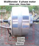
Sorry about the confusion regarding the motor. We used to offer the smaller 3 phase MiniMonster that Bluefang used on his green bike. It was out of production and we sold off the factory's old stock, and they aren't available anymore. MidMonster is what we have been talking about in this thread. We have a handful of MidMonsters stateside, which we purchased from the factory with damaged rims. It was several model years of motors sitting on the shelf and unusable, so they may vary in specs. Here's a pic with dimensions of the current model after cutting off the rim, and weighed just over 11kg. Only the new model is what I am working with in Costa Rica. I removed another .5kg from what is pictured by removing much of the aluminum covering the magnet backing ring, and I'll post another pic and new dimension after maximum weight reduction.
MidMonster with dimensions.JPG

Our 3rd motor is the larger HubMonster, which weighs 15.6kg without the rim, and it's thinner steel shell makes weight reduction more difficult, though 1kg should be simple by removing the rim flange and much of the longer brake disc mount. I don't want to confuse the issue unless you want me to post it's dimensions too. It's slightly larger but can easily be trimmed to an OD of 207mm, but can probably be cut to a narrower width at the axle, because they make it for similar width at the flats to fit standard scooter swingarms but it requires a much longer protruding brake disc mount for clearance with much wider scooter tires. If you're willing to accept the few kg weight penalty, HubMonster's advantage would be that it's much lower phase-to-phase resistance (16mOhms vs 45 for MidMonster) and 28% greater torque per amp, would allow you to run it at below 100V and achieve the same high efficiencies in your power range as MidMonster. Higher voltage is still better for it, but running below 100V opens up more controller options, including sine wave. It would also give you the flexibility to later put it on something further into the motorcycle end of the spectrum, though you'd definitely want to go high voltage for that.

Regarding cooling fans, the stators of these motors fill the shell, so there's no room for fans. The motor is easily turned into it's own fan to self ventilate if you end up pushing it hard enough to need it. MidMonster has a cooling advantage without opening, because the thick aluminum shell allows heat sink fins to be cut into the shell, however in a mid-drive the motor is easily shielded, so don't be too concerned about opening to the elements, especially when the resulting 20-30°C cooler stator means creating 8-12% less heat at a tiny cost in terms of motor drag. A lot of us run open motors in wheel without ingesting crap into the motors, and look how open alternators and non-hub motors are, so don't be too resistant to opening it in the future. I am only going to run mine sealed at first in order to get the temp info, so I can compare to running them vented.

Regarding batteries, I've seen a number of recommendations not to exceed 135V with 120V controllers. 32 in series of 3.7V nominal cells is 134V fresh off the charger at full 4.2V/cell charge, and even numbers end up more convenient especially when it comes to chargers (eg use 2 far cheaper chargers each covering half of the voltage range). Especially when it comes to high power it's best to stay conservative with voltage limits, so I recommend staying well away from the absolute maximum fresh off the charge limit the controller factory is telling me is 150V. A 6-10% increase in voltage doesn't do enough to risk reliability, so 32s of 3.7v nominal cells is fine.

Which cells to use is the million dollar question, and budget is really the deciding factor now. I have all kinds of batteries including 18650's of different types. The highest energy density stuff is definitely in the modern 18650's. Of course with any battery choice you have to consider their current handling. My only recommendation if going the 18650 route is to buy them already tab welded to avoid soldering directly on cells, and getting them in tab welded blocks makes pack assembly quite simple with the only risk being if one cell goes it means removing the block, because you can't easily determine the bad one in the parallel group. Bad cells are generally a real pain to remove from any pack unless you're using large capacity cells like 20ah A123AMP20's or 33ah cells from Nissan Leaf packs among others.
 
Back
Top