Mixing chemistries for most economic performance and range

bearing said:
swbluto said:
And, the ping's and a123s are definitely of different chemistries. Same foundations, but they definitely have different chemical make-ups. Once you mastered mixing those, then mixing others chemistries would be a cake-walk like extension.

Hm, I'm not sure about that. Both are LiFePO4. What's your source?
Their discharge curves are almost identical.

http://endless-sphere.com/forums/viewtopic.php?f=14&t=5362&p=102163&hilit=Ping+2.0+Reports+discharge+curve#p102163
http://www.zeva.com.au/tech/LiFePO4/images/A123-discharge-1.0ohm.jpg

Well... I can say the anode is different from GGoodrum's observation that a high floating voltage is maintained on the undamaged a123s whereas that's not true for others. Also, the a123s lithium crystals are smaller although that's not fundamentally different other than a higher total amount of molecular surface area per amount of lithium(Which means greater current). Also, the a123s seem to be a lot more steep and sudden near their cutoff than the ping's for the same current comparisons... but for "comparable currents" adjusted to their internal resistance, they might be exceptionally similar... They're foundationally the same, as I stated, but their chemical make-ups would be different since they do exhibit some of these different properties.

But, even if they're "oh so equivalent", I think most of the same principles could extend to mixing other different chemistries so it's relevant. Also add in the fact I have a ping and I want some a123s for the performance boost, but not too much due to the expense, and it's especially relevant. :p
bearing said:
swbluto said:
You want to limit the charging current to prevent over-charging current of the a123s and also the excess current supplied by the pings. This is partially what the circuitry is for.

Since they both have a voltage of 3 - 3.2 V over 90% of their capacity range I don't think a charge current limiter is necessary. 0.2V / 0.030 ohm = 7A which is okay with the A123:s.

So getting rid of the charge limiter might be practical(Although you're going to have to have something to bypass the schotskies). I guess that depends. But what if you get close to the Ping's cut-off current with the additional load of recharging the a123s? Once you start getting close, I can imagine you'll want to start limiting the charging current to minimize/reduce stress on the Ping. But for practical purposes, it's possible but I can imagine that could stress the Ping battery so it's definitely worth testing.

Anyways, I'm going to run some circuit simulations soon to get a general idea of what would work and what wouldn't. I'll probably be running these simulations on Wednesday or Friday evening as I've some midterms coming Friday. If someone less busy than I would like to do similar, go right ahead.
 
Ok, I derived the equations, but it seems something's wrong with them(or I'm not using mathematica's plotting utility correctly) so instead of showing off some nice pretty graphs, I did some quick circuit simulations using Tina. I found that the internal resistance of the booster pack would have to be much lower than the internal resistance of the "capacity pack" and that the difference in OC voltages would have to be small to

1) Minimize the amount of cross-current during times when the motor is drawing low current situations(Otherwise the ping would just flood the a123s with current.).
2) So the booster pack significantly picks up its proportion of the current share during increasing load current. It seems these values would have to be specifically chosen for the range of loads and voltage can only be chosen by certain intervals...

Unfortunately, the higher resistance of the capacity pack is almost equal to the internal resistance of the "booster pack" when strung in a situation where the capacity pack has 4 times as much Ah as the booster pack. The way to make this ratio more favorably askew would be to either increase the capacity of the booster pack(kind of defeats the point of minimizing its use) or decrease the capacity of the capacity pack(Kind of defeats the point of trying to get reasonable range.). So it seems some interfacing electronics is need to optimize these things... While using charging limiters would be nice, it seems there'd need to be some circuitry on the discharge side to make this idea convenient for "conventional amounts" of batteries that'd be desired for minimizing the booster-pack/capacity-pack cost ratio while still retaining desired performance characteristics. This might be slightly different for high power motorcycles and it may not have as many problems here, but it seems to be a problem for ordinary e-bikes where the desired storage capacity is kind of close to the capacity intervals offered by a123s.
 
To bring this down to earth, How about looking at particular combinations of Ping plus A123 cells to see if the parallel combinations makes sense.

Suppose you want to minimize the cost and size for a 10 AH 36V LiFePO4 pack, but still want to be able to run at 40 amps continuous, but let's say that you don't want to spend the extra money or pack the extra weight of a 2C 20 AH Ping pack.

A 8 AH Ping is only rated to 2 continuous discharge, giving a 20 Amp max output, and if Ping will make you one, it would cost perhaps $300 for a 36V pack.

Suppose you spend another $120 to buy a Dewalt pack plus two more A123 cells to get a 12s 2.3 AH 36V pack, which can supply 30C, or easily 60A.

Put the two in parallel (at every cell) and you can easily supply 40 amps, and get a 10 AH pack at 36 V, for roughly $420 dollars, and you get the additional ability to run at much higher current for short periods of time.

The internal resistance of the Ping 8 AH cell is supposed to be about 8 mohm (version 2 is about 15 mohm/4 AH cell), and the internal resistance of a 2.3 AH A123 cell is supposed to be about the same at about 8 mohm, so put them together and they can easily share the load nicely.

Now consider trying to get 80 Amps out of a 20 AH Ping battery. If you added a single 12s pack of A123 cells in parallel, you could theoretically source 80 amps, since the A123's are supposed to be able to handle 30C discharge. But since the 20AH Ping pack is going to have about 3 mohms of resistance, and the A123's are still only 8 mohms, the Ping pack will be providing about 2/3 of the current and the A123 will provide 1/3 of the current, which means that the Ping pack will be supplying more than it's rated 2C discharge current! So apparently, this combination does not make sense.

Therefore, instead, you could add a set of 12s2p A123 cells in parallel with your 20 AH Ping pack cells , for a 24.6 AH 80 amp pack. Of course, you'd need to replace or modify the Ping BMS to handle the additional current.


Brian
 
Those quick calculations are nice to get an idea of what could be done, but it's not very useful for getting a complete description of all the nuances involved, including the currents from each battery at a given amount of load current and different charge states of the batteries. That's why this "Up there in the clouds" equations are needed, as they expedite realistic calculations for all facets of the system for any given mix of batteries. Anyways, I looked over the formulas I entered into mathematica and it appears I accidentally used a minus sign when a positive sign was meant. After the correction, the graph's values are realistic(I.e., two identical batteries in parallel split the load current evenly and the load is correct and everything.).

The horizontal-axis it the "controller+motor's" effective resistance and the vertical axis is the current. The yellow line is the load current, the blue the hypothetical "capacity pack" and the purple the "booster pack". The more rightward you go, the less current the motor+controller is consuming as you can see so you can see how the capacity pack starts to charge the booster pack at those values.


The subscript "a" refers to "Battery A" and "b" refers to the "Battery B". "l" and "L" refer to the load(R_l is the effective resistance of the controller/motor as the battery sees it and I_l is the amount of current going to the controller.), and Va is battery A's open-circuit voltage and Ra is Battery A's internal resistance and correspondingly for Vb and Rb.

View attachment BoostCapacityEquations.bmp


To be able to know how the system reacts at different levels of charge, I'd have to know what the Open Circuit voltage for the batteries are at different levels of charge. The graph contains educated guesses for a "45 volt" 10ah ping battery(capacity pack) and a "42 volt" 2.3 ah a123 battery at half-full charges.

Oh, the set-up is basically two batteries in parallel with their own special internal resistances with a single effective resistance that represents the effective resistance of the motor/controller. As simple as you can get.
 
I think I have a way of inferring the open circuit voltage and internal resistance of the battery at different states of charge(How full the battery is) just by looking at discharge curves!

The formula for internal resistance is pretty standard. Just do (V_2-V_1)/(I_1-I_2) for two different discharge curves. Do this at different points of states of charge to find the relation between internal resistance and state of charge. I think the internal resistance would increase as the battery becomes increasingly discharged, but I've heard that the a123s are specifically engineered so that it stays constant?

For the open circuit voltage at different states of charge, just use the previously acquired internal resistance at a given state of charge and add on the current*internal_resistance(The voltage drop across the battery's internal resistance) to the output voltage at that given current. Voila, the open-circuit voltage and state of charge formula.

Now, I don't think this is 100% accurate for current-stressed batteries as it seems batteries have a weird reversal in internal resistance at relatively high load currents(You can see this as the voltage initially drops and then slightly recovers as it discharges and then drops off the map when it's getting depleted.), but it should be reasonably accurate for practical purposes with "normal" currents. Anyways, now I need a123 and ping discharge graphs!


Edit: I think I might have reasoned the mechanism for this weird reversal. For batteries, generally the internal resistance goes down for higher temperatures for the battery, so at a high enough current, your initial internal resistance will be higher than it will be after the battery has had enough time to significantly heat to a higher temperature(And larger currents mean greater heating), which means the output voltage will dip at first but then recover. Since an additive affect on the internal resistance comes from the depleted charge(or something associated with it), eventually the internal resistance increases which causes an increasing voltage drop as it nears depletion. So that's what explains the gradual flattening and then reversal of the output voltage at the beginning of the discharge curve for increasing discharge currents.

Edit again:

I think I found the a123 graphs!

View attachment A 123Systems 2300 Li-Ion.jpg

Now i just need to find "easy to use" Ping graphs. I've seen the ping graphs linked to earlier from ZapPat, but it seems that it uses the time along the horizontal axis instead of Ahs. While I could easily calculate Ah as a function of time(Since they're constant current graphs)... I don't wanna. Well, it's actually easier than I originally thought, so I might if that's my seeming only option.
 
Boy you guys sure over think this stuff. I would be riding with it by now.

Aerowhatt
 
Haha! Well, I haven't made the order yet! :lol:

I'd like to know exactly what I need to order before ordering, you see, in the spirit of keeping the total cost as low as possible.
 
I'm not understanding the theory completely, but looking at the previous posts it's looking like simply putting Pings & A123s in parallel & expecting them to behave as we want (A123 supplying the big currents but pings supplying the general low current demands) is either difficult or uneconomic...

So it's time to turn to electronics (which I'm also not too hot at :) )

Anyway if we split up the problem into a) Discharge and b) Charge. First we use Schotkies to isolate the 2 batteries so that one doesn't charge the other except thru our future "charging circuit".

a) Discharge

How about something like this (cue crappy ASCII art).
(The idea is only one battery is used at a time.)


BAT A -----> SHUNT----> FET/Relay ----> Schottky-----\
.................|.............................................|
...............LOGIC.........................................+ CAPACITOR ----- LOAD
.................|.............................................|
BAT B ------>SHUNT----> FET/RELAY-----> Schottky----/


BAT A is our low load batt (i.e. Ping)
BAT B is our high load batt (i.e. A123, Lead Acid, NiCd etc)

The shunts are used to measure the loads. The logic turns on the FETs/(Huge)Relays depending on the loads thru the shunts.
The idea is only one battery is used at a time.
So the logic says when LOAD(A) > limit switch on FET(B) and switch off FET(A).
When the load falls back < limit switch off FET(B) and switch on FET(A) again.
The Capacitor smooths out the transition.
Are the Schottkies still needed? (The FETs will provide isolation is the logic works)
You need some hysteresis in the logic.

b) Charging
Only need 1 charger

BATA ----> FET ---> BAT B
..............|..........|
..............L-- Voltage Detector

Not sure of this but basically you need a voltage comparator on BAT B. If the voltage on BAT B is less than fully charged, turn on the FET/Relay.
You would probably want some logic to inhibit charging if BAT B is in use.

Does this work as a concept?

(You could use PWM on the discharge FETs to "share" the load, but this gets complicated. I suppose using a PIC or something as the logic would help here though)


Cheers

Steve
 
It sounds plausible and it's roughly similar to a sketch I made a few days ago. I was just in the midst of determining the practicality of using an "optimized" combination of low-load and high-load batteries just going strictly parallel by trying to derive the exact formulas which could be used for a simulation, but it does seem increasingly evident that the "optimized combination" wouldn't behave nearly like what we'd want so perhaps I should stop searching for the optimized combination and focus on the electronic mixing.

To test out the idea, I'll probably be doing some circuit simulations to see how it goes. I can possibly "tape the simulations" so you guys can see how it would go as well, but I'll determine the inconvenience of that later.

From initial impressions, if you turn off one battery and then turn on another battery, there's a "gap" where there isn't any current being contributed by the batteries and that worries me with the potentially very quick voltage drop from the capacitor. Though, I could imagine that the gap would be minimized so it could be a practical circuit with the appropriate capacitor.

The seemingly "safer" approach would be to use the schottkies on the output side, and then turn on the high current battery while the low current battery is on, and then turn off the low current battery.

The logic would be a piece of cake with one of these microcontrollers I have with the appropriate shunts and interfacing components with the mosfets. It seems most power FETs fully turn on at around 12-13 volts, and a simple microcontroller(Well, the atmegas anyways - the kind I have) only outputs 5 volts so it seems an op-amp might need to be used. Or a "voltage multiplier" or some such.

Also, the "sharing the load with PWM" idea sounds incredibly interesting. Do you have a concrete idea of how that could be implemented? I can get practically any square-wave desired from the microcontroller, so I imagine the PWM signal wouldn't be a problem.
 
swbluto said:
It sounds plausible and it's roughly similar to a sketch I made a few days ago. I was just in the midst of determining the practicality of using an "optimized" combination of low-load and high-load batteries just going strictly parallel by trying to derive the exact formulas which could be used for a simulation, but it does seem increasingly evident that the "optimized combination" wouldn't behave nearly like what we'd want so perhaps I should stop searching for the optimized combination and focus on the electronic mixing.

To test out the idea, I'll probably be doing some circuit simulations to see how it goes. I can possibly "tape the simulations" so you guys can see how it would go as well, but I'll determine the inconvenience of that later.

From initial impressions, if you turn off one battery and then turn on another battery, there's a "gap" where there isn't any current being contributed by the batteries and that worries me with the potentially very quick voltage drop from the capacitor. Though, I could imagine that the gap would be minimized so it could be a practical circuit with the appropriate capacitor.

The seemingly "safer" approach would be to use the schottkies on the output side, and then turn on the high current battery while the low current battery is on, and then turn off the low current battery.

The logic would be a piece of cake with one of these microcontrollers I have with the appropriate shunts and interfacing components with the mosfets. It seems most power FETs fully turn on at around 12-13 volts, and a simple microcontroller(Well, the atmegas anyways - the kind I have) only outputs 5 volts so it seems an op-amp might need to be used. Or a "voltage multiplier" or some such.

Also, the "sharing the load with PWM" idea sounds incredibly interesting. Do you have a concrete idea of how that could be implemented? I can get practically any square-wave desired from the microcontroller, so I imagine the PWM signal wouldn't be a problem.

Cheers, nice to know I'm not completly mad! ;)

As far as PWM is concerned, I was thinking of a simple scheme of a clocked microcontroller. If we have 10 clocks per "cycle" we just distribute the clocks to A or B battery as appropriate (maybe using a fixed table to determine how to disribute according to the loads detected). So for 20% A and 80% B we just hold FET A on for 2 and FET B on for 8.(Sorry I'm not explaining it well!). If the clock is fast enough so that 10 clocks isn't too slow it should approximate to PWM?
 
torrent99 said:
swbluto said:
It sounds plausible and it's roughly similar to a sketch I made a few days ago. I was just in the midst of determining the practicality of using an "optimized" combination of low-load and high-load batteries just going strictly parallel by trying to derive the exact formulas which could be used for a simulation, but it does seem increasingly evident that the "optimized combination" wouldn't behave nearly like what we'd want so perhaps I should stop searching for the optimized combination and focus on the electronic mixing.

To test out the idea, I'll probably be doing some circuit simulations to see how it goes. I can possibly "tape the simulations" so you guys can see how it would go as well, but I'll determine the inconvenience of that later.

From initial impressions, if you turn off one battery and then turn on another battery, there's a "gap" where there isn't any current being contributed by the batteries and that worries me with the potentially very quick voltage drop from the capacitor. Though, I could imagine that the gap would be minimized so it could be a practical circuit with the appropriate capacitor.

The seemingly "safer" approach would be to use the schottkies on the output side, and then turn on the high current battery while the low current battery is on, and then turn off the low current battery.

The logic would be a piece of cake with one of these microcontrollers I have with the appropriate shunts and interfacing components with the mosfets. It seems most power FETs fully turn on at around 12-13 volts, and a simple microcontroller(Well, the atmegas anyways - the kind I have) only outputs 5 volts so it seems an op-amp might need to be used. Or a "voltage multiplier" or some such.

Also, the "sharing the load with PWM" idea sounds incredibly interesting. Do you have a concrete idea of how that could be implemented? I can get practically any square-wave desired from the microcontroller, so I imagine the PWM signal wouldn't be a problem.

Cheers, nice to know I'm not completly mad! ;)

Let's hope that it's not a Folie à deux. :wink:

As far as PWM is concerned, I was thinking of a simple scheme of a clocked microcontroller. If we have 10 clocks per "cycle" we just distribute the clocks to A or B battery as appropriate (maybe using a fixed table to determine how to disribute according to the loads detected). So for 20% A and 80% B we just hold FET A on for 2 and FET B on for 8.(Sorry I'm not explaining it well!). If the clock is fast enough so that 10 clocks isn't too slow it should approximate to PWM?

Sorry, I don't understand. I'm looking up current limiting using PWM so it's probable I'll eventually find a compatible circuit, and controllers use PWM methods to limit the current from batteries so there's likely some analog. Another way to "share the load", methinks, is to adjust the gate voltage so that the source-to-drain resistance of the mosfet is great enough to ensure a decided current limit on a given battery(More importantly, BAT A, the "capacity pack".), but this type of linear regulation may potentially dissipate a lot of heat, especially for higher currents so a PWM circuit sounds like it'd be particularly better in this regard.
 
swbluto said:
As far as PWM is concerned, I was thinking of a simple scheme of a clocked microcontroller. If we have 10 clocks per "cycle" we just distribute the clocks to A or B battery as appropriate (maybe using a fixed table to determine how to disribute according to the loads detected). So for 20% A and 80% B we just hold FET A on for 2 and FET B on for 8.(Sorry I'm not explaining it well!). If the clock is fast enough so that 10 clocks isn't too slow it should approximate to PWM?

Sorry, I don't understand. I'm looking up current limiting using PWM so it's probable I'll eventually find a compatible circuit, and controllers use PWM methods to limit the current from batteries so there's likely some analog. Another way to "share the load", methinks, is to adjust the gate voltage so that the source-to-drain resistance of the mosfet is great enough to ensure a decided current limit on a given battery(More importantly, BAT A, the "capacity pack".), but this type of linear regulation may potentially dissipate a lot of heat, especially for higher currents so a PWM circuit sounds like it'd be particularly better in this regard.

Yes, linear regulation is going to dissipate loads of heat and really isn't a good idea!

With PWM the clue is in the name, Pulse Width Modulation.
So you PULSE the signal. And to Modulate it you vary the Width of the Pulse. (sorry if I'm teaching you to suck eggs here I like to be super clear ;) ).

So with my simple scheme above, if you have 10 clock beats on the PIC, and you wanted 20% on A and 80% on B. For 2 of those clock beats you have FETA on and for 8 you have FETB on. Then you repeat the pattern.
If we want 70% A and 30% B you FETA is on for 7 beats and FETB is on for 3 beat etc. etc.

So if the PIC clock is running at say 1MHz then 10 clock beats is 100Khz, so we'd be switching the FETS on and off at 100Khz but varying the width of the pulse i.e. PWM. (This is probably way too fast to be switching the FETS we probably want to be aiming for more like 10Khz I suspect, easily modifyable by using say 100clock beats instead of 10 etc I would also add capacitors on each battery B4 our circuit to smooth out the current spikes).

We don't want to do any maths inside the PIC if we can help it, so its probably best to use some sort of lookup table to decide given the TotalCurrent what width of A pulse and B pulse to use. Here's some pseudo code:
TotalCurrent = CurrentA + CurrentB;
If TotalCurrent <=5 amps THEN WidthA= 100% WidthB=0%
If TotoaCurrent >5 amps and <10amp THEN WidthA = 20% WidthB=80%
etc
If TotalCurrent>15amps THEN WidthA=0% WidthB=100%

simples...

BTW are you able to run your simple parallel circuit simulations with something like NiMh, NiCd or Lead Acid? NiCd and LeadAcid *really* are cheap and can also deliver mega current...
 
Well guys, your split PWM will work for sure, but I'm not really sure that this would really be necessary. Simulation might be interesting, but it may be a bit hard to reproduce the funny behaviors a cell can display. Non-linear internal resistance, complex temperature relationships, etc, might make accurate simulation a pain.

Maybe the best would be to do some charge/discharge tests using only a single cell setup (in the case of similar chemical formulations) with a couple Amp-meters. I would try it, but I don't have any A123's nor cheap single cell LiFePO4's.

It gets more complex when mixing different chemistries, and would then have to be done on the battery level (vs cell level possibly for same chems). This may be when the PWM idea might come in usefull. Torrent99's idea is good for sure, and would not be too complex to do using an MCU. However, I would never have one string at 0% and the other at 100% since this would defeat the purpose of having parallel strings to share the load. Just limit each string's max discharge current to whatever each can handle, but always using both to get a total current higher than either alone could provide.

One problem I can see with having two paralleled strings and seperate PWM FETs, is that the internal FET diodes will start conducting if one pack's voltage is higher than the other by the FET's voltage drop, even if that other's FET is off. Seems like you might need two back to back FETs to avoid this, which also would double your FET losses and make the FET drive circuit more complex. I might be totally wrong here though, since I've not mused much about this yet. I do have about 4 kWh of NiMh cells here with rather lame internal R though, so this idea is interesting to me...
 
Torrent99, yeah I understand the basics of pulse modulation and I think I understand the same basic idea you're trying to convey, but I'm trying to conceive of a circuit design that would draw a current upto a certain current limit at a steady current from a given battery. With my impromptu circuit, the current from the battery just varied from no current to some current as the individual mosfets turned on and off which is oscillation I don't think would be desired, so I'm thinking there's a better way(An obvious way to someone else) to implement this I'm just not seeing.

View attachment RoughDraftPWMcircuit.bmp

The circles hanging off the side of the battery's branches are the driving PWM signals to the mosfet's gate.

I also don't understand how you'd plan to limit the current to a given limit using a constant pre-determined duty cycle. Such a thing seems to me that'd it'd just try to maintain a certain proportionality of current from each respective battery. As the load current would vary, you could get a high enough proportion of current for the "capacity battery"/BAT A that'd exceed the predicted load current, and it also doesn't seem like it'd take full advantage of bat A at lower load currents that exceed A's current limit. That's why it seems having active feedback would be the most adaptable to changing parameters to get the desired response and I don't think it'd be too hard to program.

Also, the circuit simulator doesn't allow non-constant internal resistances as far as I know. This would be most important for a chemistry like Lead which has an exponential internal resistance in relation to current. You could, however, adjust the resistance on the fly in the middle of the simulation.

If I were to program my own circuit simulator, making chemistries like Lead and Nimh(and so on) work would be relatively easy as long as an accurate mathematical model for it exists(As does for lead with Peukert's law). Also, temperature affects would complicate it and that data doesn't seem to be easily publically available, but for the sake of a simulation, I think "normal running temperatures" are good enough. If it's a circuit that has some kind of active feedback, it really shouldn't matter what the temperature is(Within reason).
 
ZapPat said:
However, I would never have one string at 0% and the other at 100% since this would defeat the purpose of having parallel strings to share the load. Just limit each string's max discharge current to whatever each can handle, but always using both to get a total current higher than either alone could provide.

For the first sentence, how would you avoid that condition if you were climbing a sufficiently tall hill? Or would you just avoid sufficiently tall hills or you would ensure you'd have enough of a booster pack to climb sufficiently tall hills at a reasonable speed? If the latter, then that seems reasonable.

And, for the second sentence, I agree and I think that's one of the predicted main advantages of the PWM idea. "Load sharing" upto a certain amount of load(being the sum of the two max currents from each battery.).
 
ZapPat said:
Well guys, your split PWM will work for sure, but I'm not really sure that this would really be necessary. Simulation might be interesting, but it may be a bit hard to reproduce the funny behaviors a cell can display. Non-linear internal resistance, complex temperature relationships, etc, might make accurate simulation a pain.
Thanks! It's good to know we're on the right track.

However, I would never have one string at 0% and the other at 100% since this would defeat the purpose of having parallel strings to share the load. Just limit each string's max discharge current to whatever each can handle, but always using both to get a total current higher than either alone could provide.
So always keep a trickle thru each one? I would hesitate to keep the B channel always fully on, as by our definition that's the "premium" high grade stuff that's in short supply...so personally I'd only want to use it to supplement the A channel. (however see below)

One problem I can see with having two paralleled strings and seperate PWM FETs, is that the internal FET diodes will start conducting if one pack's voltage is higher than the other by the FET's voltage drop, even if that other's FET is off. Seems like you might need two back to back FETs to avoid this, which also would double your FET losses and make the FET drive circuit more complex. I might be totally wrong here though, since I've not mused much about this yet. I do have about 4 kWh of NiMh cells here with rather lame internal R though, so this idea is interesting to me...

Would keeping the Schottkies mean we don't have to use 2 FETs per channel?

I think having the basic control circuit is the important thing, then by programming the MCU we can come up with whatever PWM scheme we like to control how the available current is shared out...

Unfortunately that's where I reach my limit, 15 years ago I graduated in Computer Engineering specialising in VLSI design.... that was 15 years ago. I've not used it since so I'm afraid my electronics is now very limited... and power electronics zilch.

Over to you guys!
 
I wasn't originally thinking of SLAs with this project, but then I remembered how much the cycle life of SLAs increases with decreasing currents and, wow, this could actually make the "long term costs" of the battery component really low and potentially noticeably increase range of SLA systems while maintaining good performance. Of course, projects that favor weight minimization as opposed to cost minimization and don't require much batteries to begin with would be less impacted by this(Electric bicycles and the such), but this could really impact the cost of batteries where weight isn't as much of a concern, such as motorcycles and electric vehicles. It might actually make around-the-town-and-on-the-highway-short-distances electric vehicles long-term cost and performance competitive with gasoline vehicles. As far as highway speeds, the power demands are usually pretty high relative to other common vehicular demands so the benefit of a small "booster pack" becomes less apparent and I'd imagine the range would still be limiting on the highway(Like under 50 to 100 miles). I guess that's when we need to kick in the generator, eh? :lol:
 
I was doing a little of analysis on a black-box circuit with the desired properties. This "black box" would one that'd be fit onto each battery branch to regulate the current(the capacity pack being the more urgent of the two), and I imposed on it the "conservation of power" (which is a property we'd attain with the highest possible theoretical efficiency: 100%) to solve the equations, and I realized for a given load resistance(used to symbolize the controller/motor - Please tell me the controller has negligible reactance?), the output voltage would have to be decreased to get the input current into line/limit it to its chosen max current. So, I fired up the simple simulation of the two batteries in parallel, put the load resistance to a small value so that the load would exceed the hypothetical capacity battery's limit, and manually lowering the capacity battery's output voltage and it surely enough gradually lowered its current so I can imagine this might be a mechanism to controlling the current - Lower its output voltage using some kind of switching circuit(And use some of feedback mechanism to limit it). It seems like any of the normal step-down switching converter topologies might work, however, I'm not sure if it's desired for the input voltage(i.e., the battery side) to be turn on and off at least hundreds of times a second. Would "pulsing" the battery's output hurt it? Is there a switching converter that'll lower the input voltage to a smaller output voltage(or similar efficiency scheme) without disrupting the input or output current to this converter at steady state? I'm looking at the converters now but I'm not generally expecting any of the "normal" ones to have a continuous input current. Maybe they do, but I don't know.

I've extended the question to the electronics forum: http://www.dutchforce.com/~eforum/index.php?showtopic=24958&st=0&#entry211059
 
Switching is what all modern speed- and current regulators do; I don't think thats a problem.

I think you're looking for a buck-regulator. It will probably need quite a big inductor though, because of the high currents. But the size is also dependent on the switching frequency; higher frequency means lower inductor value for the same current ripple.

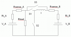
Maybe something in the line of this: (Switches are transistors, S3 is optional. S2 can be a diode, but with added losses.) (The "I" is supposed to be an L)
 

Attachments

  • batterybuck.GIF
    batterybuck.GIF
    6.6 KB · Views: 1,842
Yeah, probably. I have a feeling this technology is very quickly going way over my head in regards to my intuitive knowledge of electronics. *sigh*

I'll try playing around with the idea. I don't immediately see how Bat A's current is being limited since it's directly attached to the load, but I guess that might be the intent assuming Bat A is the high-current pack? Also, when you say s2 can be a diode, does that imply that... that the s2 would on at all times except when the current is being reversed? Or is there a FET out there that has a more efficient body diode? Also, I'm guessing S1 limits the current from Bat B depending on its duty cycle and S3, being the optional one, might help limit the current somehow?
 
All switches would be controlled by a microcontroller or by a switch regulator IC with a few other components. Pack A is the high capacity/low current one.

The normal state would be to have S3 closed and the others open - bypassing the buck regulator. Packs then acts like they are directly connected.

Based on some criterias the regulator will open S3 and start limiting the current into pack B with the buck regulator. The buck regulator operates by alternatively switching on S1 or S2 in a high speed, like 100 kHz or more.

The criteria may be that the charge current is to high. Another criteria may be that the regulator senses a current going into pack B at the same time as a (too) high current leaving pack A.

S2 can be diode because when S1 opens the inductor will induce a negative voltage, which will go through S2 if it is a diode. Since there is voltage lost over a diode some energy will become heat.

If the current from pack A has to be limited then another switch and/or buck regulator has to be used.


I don't like the idea of involving this kind of of electronics though, because it's lossy (maybe also expensive and heavy, with the inductor). I still think the straightforward method is the best; connecting the batteries in parallel, pre BMS.
 
bearing said:
All switches would be controlled by a microcontroller or by a switch regulator IC with a few other components. Pack A is the high capacity/low current one.

The normal state would be to have S3 closed and the others open - bypassing the buck regulator. Packs then acts like they are directly connected.

Based on some criterias the regulator will open S3 and start limiting the current into pack B with the buck regulator. The buck regulator operates by alternatively switching on S1 or S2 in a high speed, like 100 kHz or more.

The criteria may be that the charge current is to high. Another criteria may be that the regulator senses a current going into pack B at the same time as a (too) high current leaving pack A.

S2 can be diode because when S1 opens the inductor will induce a negative voltage, which will go through S2 if it is a diode. Since there is voltage lost over a diode some energy will become heat.

If the current from pack A has to be limited then another switch and/or buck regulator has to be used.


I don't like the idea of involving this kind of of electronics though, because it's lossy (maybe also expensive and heavy, with the inductor). I still think the straightforward method is the best; connecting the batteries in parallel, pre BMS.

Bearing,
Thanks for the explanation, I was wondering how this worked.
However, either I'm misunderstanding or I think we're attacking different parts of the problem...

To recap the idea is 2 have two sorts of battery:
1) BAT A - Loads of capacity, but low C rating. Cheap. e.g. Ping can deliver 1-2C depending on who you speak to.
2) BAT B - Limited capacity, large C rating. Relatively expensive (in money/weight/bulk etc) e.g. A123/Lead Acid etc can delive LOADS of Current for short time.

There's also 2 parts to the problem:
1) Discharge.
2) Charge

Discharge:

So the idea is to use BAT A most of the time. When we need a nitro boost to tackle a section of hill, add in BAT B.
There are several strategies on how to "mix the currents":
a) All or nothing. Either BAT A is on or BAT B is on.
b) Limit A. BAT A supplies up to a defined limit. BAT B supplies the rest.
c) Natural. Just connect BAT A & BATB and let nature take it's course, hopefully BAT A won't exceed its limit...

Charge:

If B is much smaller than A, then we might want to use A to recharge B when we're not using B. Obviously having gone to the effort not to overstress A in the discharge case above, we'd ideally like to limit how much current from A we use to recharge B.

I'm mainly thinking about the discharge portion...Does this agree with your ideas on using the buck regulator?

Cheers

Steve
 
In the sketch above the discharge would be natural and the charge would be controlled. I can see now that it wasn't really what you were looking for.

Maybe putting the load in parallel with the high current battery would be better, yes I think so. S3 wouldn't be needed.

With that approach discharge would be "b) limit A" and charge would still be controlled. If I'm not mistaken that is all you have wanted.
 
Back
Top