motor cuts out , controller gets hot .

fevitz

10 W
Joined
Feb 10, 2015
Messages
77
Location
gold coast australia
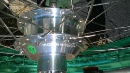
WP_20150919_003.jpgWP_20150919_004.jpgIm having a problem with my new build and need some advice to get things right . The motor is a 36v 450w 261rpm / the controller is 24/36/48 compatable as is the LCD display . The battery is a 48v lifepo4 . Ive just taken it for its first test run and it keeps on cutting out . I only went around the block , the throttle cuts out immediately as the motor kicks in and when I release it and apply , it kicks in for a second then cuts out . It continually does this on and off ,,,,its also noisy but I guess that's vibration in the bike itself . I had only travelled 1/2 mile when I returned the controller was very hot and the wheel / motor was warmish !
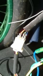
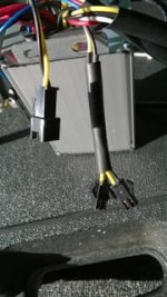
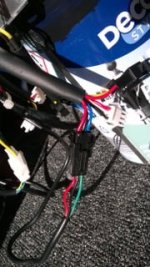
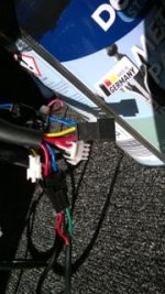
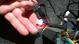
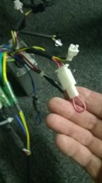
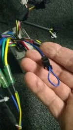
Could this be a PAS wire I need to disconnect as I have not connected the PAS up . Here are a couple of photos of the wiring from the controller . There were no directions with how to connect this as I bought all parts separately online . The power is coming from the battery to the motor , its just that the motor and controller are getting hot and the power to the motor keeps on cutting out . I can supply a better detailed picture of the controller if needed .
many thanks rick
 
You have a Kunteng display, so I can only guess that you therefore have a KT controller, which doesn't have self learning. You have to find the correct connection sequence for the 3 phase and 3 hall wires. They don't necssarily go colour to colour. You have a false positive at the moment, which means tht the motor is turning, but the timing of the pulses is incorrect. That is why the motor is vibrating, running inefficiently and drawing huge current.

If you look in the wiki, there's a chart to help you find the correct sequence quicky, otherwise do all 36 combinations and use the best one of three that makes the motor work correctly.

Show us which motor and contoller you have. That would be more helpful than showing us a couple or irrelevant connectors, one of which is the optional cruise that you should disconnect. It won't affect your present problem, but you need to understand the constraints and operation of the cruise before you try and use it if you like to live.
 
D8veh , yes I joined the hall & phase wires colour to colour , I hear what your saying about that . The motor IS vibrating , running badly and 1 of the bars on the battery LCD display went off the screen showing quick battery drainage .Of all the 6 coloured wires only 5 of them have connectors , the white wire was without one "should I connect it up?" Thank you for you astute observation , im sure this motor will run very well when its set right

The throttle = red , black , green , it looks like I have 3 choices of connectors to choose from . I currently have them with the RED , BLACK , BLUE , this looks right !

The motor = 36v260RPM15070184

The controller = model KT36/48svprd - SLS02D ,rated v = dc36v/48v , current rated = 11A , max current = 22+1A , speed set 1-4 . 2v , brake input low level DC30/40+0.5v

The 2 yellow and black wires + 1 yellow & black connector , should these bee joined up ?

One more thing ive noticed with this motor and that is it has the power connector on the left side fork , but I need that for the disc brake


Thank you docw009 ,,ill try some combinations from your link .

rick


View attachment 7View attachment 6WP_20150921_018.jpgWP_20150921_007.jpgWP_20150921_009.jpgWP_20150921_002.jpgWP_20150921_003.jpgWP_20150921_004.jpg
 
You have a false positive result spinning forward. Swap 2 of the halls or 2 of the phases (any 2...only 2) and then don't touch them. If you swapped 2 halls, then go find the right combination of the 5 remaining possible phase wire combos using small throttle pulses with each attempt. The one that spins up in forward smoothly is the good one. Take a short easy test ride to be sure, and you should notice a marked improvement. If you swapped 2 phases at the beginning, then you would go find the right combo of the remaining 5 possible of the hall wires.

That's the easy way, so don't bother with flow charts or spreadsheets and you'll get it in 5 tries or less. It's easiest to just change 2 wires at a time, and keep track to be methodical. The best way to do that is pick an anchor wire...eg controller green. You have green on the green now, so swap the yellow and blue. If that doesn't work, move the yellow to the controller green and try. Then swap the motor blue and green. If still a no go move the blue to the controller green and try. Then swapping the motor green and yellow covers all the possible.
 
I played with the phase wires & halls . I did manage to get the throttle to stay on with the motor and with the front wheel off the ground , and it seems to be running smoothly , but the controller got very hot after only 2 minutes of it going at high speed . to fix this overheating is more plying around required ? or could it be something else ?
Heres the combination ive set it at to get it to run at approx. 30kph (19mph) I also expected it to go faster than that .
CONTROLLER SIDE PHASE = BLUE - GREEN
YELLOW - YELLOW
GREEN - BLUE

CONTROLLER SIDE HALLS = BLUE - BLUE
GREEN - YELLOW
YELLOW - GREEN

rick "gold coast Australia"
 
Yes, you need to try more combinations until it runs smoothly and cool.

The yellow and black wires (two together) are for the brakes. The unconnected white wire is for the optional motor speed sensor. You need to use a wheel-speed sensor if you want the display to show the speed correctly.

You can find a wiring diagram to download at the botom of the page on the BMSBattery.com listing of their S12S controller, but it won't tell you the hall/phase connection sequence.

There's some settings that need to be set right. If you bought your controller and motor as a kit, they should already be set by the seller, who should also be able to tell you the correct connection sequence. Don't change any parameters without writing down what they're already set to. A few people did a reset to defaults, which changes everything, so don't do that. The parameter that might affect your problem is P1, which I think can affect the timing, so, if you can't find a sequence that solves your problem, have a look at P1.
 
Slow is probably the right wiring, so don't touch them again until you're sure. Wiring has 3 possible results, correct, false positive (a very advanced timing with low torque and high wheel off the ground speeds but slow riding with lots of heat), doesn't work at all.

You could have something restricting speed, but 20mph with a small motor on an ebike is pretty typical.
 
I bought the motor , controller , LCD and throttle separately from the same company "sunwaycycle" aliexpress . The battery a 48v , I already had . Ill just go through all wire colour combinations writing each down as I go first , then if no solution (p1) is next . I may even ask sunway if they may have a quick fix as they sold me all the parts . Im enjoying all this anyway ,,,,,,,,,,!
rick
 
There’s simply no standard color code between motors/controllers and it’ll drive you nuts trying to keep track of it. Much better off learning how to “find” proper phase/hall combinations without cooking your electronics.

Here’s some links I prefer for this topic:

http://www.ebikes.ca/learn/troubleshooting.html

https://endless-sphere.com/w/index.php/Determining_the_Wiring_for_a_Brushless_Motor
 
Ykick said:
There’s simply no standard color code between motors/controllers and it’ll drive you nuts trying to keep track of it. Much better off learning how to “find” proper phase/hall combinations without cooking your electronics.

Here’s some links I prefer for this topic:

http://www.ebikes.ca/learn/troubleshooting.html

https://endless-sphere.com/w/index.php/Determining_the_Wiring_for_a_Brushless_Motor
hI Y,KICK , Ive tried all 36 combinations using the graph in your link , but its not getting cool , heres what ive found with the front wheel raised off the ground floor in the garage .
HALL WIRES ;
CONTROLLER SIDE B,G,Y - MOTOR SIDE B,Y,G TO PHASE CONTROLLER SIDE B,G,Y - MOTOR SIDE B,Y,G
********************** B,G,Y -**************** Y,G,B TO PHASE CONTROLLER SIDE B,G,Y -**************** Y,G,B
********************** B,G,Y -**************** G,B,Y TO PHASE CONTROLLER SIDE B,G,Y -**************** G,B,Y
These 3 out of 36 combinations seemed to be all good and very fast speed readouts (78 kph) (44mph) . The motor and controller are getting very hot and the battery drained to nearly half after just 13 kms . 48v battery + 450w 36v motor .

There are 3 other smooth combinations going a slower (28kph) (18mph) , the motor and controller are still getting hot .
The remaining 30 combinations are (no rotation,rough forward or rough backward)
Could a problem lie elsewhere that's causing the overheating and current drain ? Apart from the battery draining quick & the overheating motor /controller problem the speeds its putting out is phenomenal , unless im getting an incorrect readout .
rick :?
 
You could have a bad Hall sensor inside the motor or iffy wire, connector?

Or, maybe there’s no problem and this is just what it is but we can’t tell based on what you’re describing. And you have little to compare it to...

Have you looked at those troubleshooting links to test Controller, Motor Hall sensors?

Btw, some newer controllers have self-learning shit and I dunno if you’ve got one of those?

What I would do at this point would be the Hall sensor test (link provided earlier) and then either buy a cheap power meter to measure current in-between battery-controller or rig a DVM with 10A DC scale to measure no load (wheel off the ground) current with WOT (wide open throttle).

If you don’t feel comfortable rigging a DVM to measure 10A scale one of these would be the next best solution - http://www.ebay.com/itm/GT-Power-LCD-130A-High-RC-Precision-Walt-Watt-Meter-Power-Analyzer-Ver-2-NEW-US-/331215821510?hash=item4d1e005ac6

A good healthy Phase power - Hall sensor combination with most motors should only draw around 2A in free air, no driving load with smooth rotation. This would be the best way to confirm you’re motor/controller’s connected and functioning correctly.
 
http://www.aliexpress.com/snapshot/6817942393.html?orderId=68497036168508

This is the controller I have , thanks and ill have another look at those troubleshooting liks

rick
 
There's something that doesn't add up. It's a 36v 260 rpm motor, which therefore will give 328 rpm at 48v. With a fully charged battery, the no load speed should be 28.5 mph, but you have combinations that give 44 mph or 18 mph. Are you sure that you've set the wheel size and the number of speed sensor pulses correctly in the LCD settings to display the speed correctly? Whichever combination gives you an actual no-load speed of about 29 mph or 360 rpm is the correct one.

If you ran with a true 44 mph combination on the road, your controller would give its maximum current (22 amps) nearly all the time, which is certain to overheat it. Even with the correct combination for 30 mph, your motor will still be drawing maximum current too much, so will get hot. It's not a big motor, so it will struggle to get over 20 mph, which would be about where the current starts to reduce from the maximum. Your photo seems to show a 6 FET controller. 22 amps is a lot for one of those, so I can see heat being a problem. It would be better for a slower motor, like 48v 260 rpm - something like a 26v 201 rpm Q128, which is similar to your motor.

Are you using the PAS? The PAS allows you to control the power with current control, so each level on the display will be a different maximum current. That doesn't apply to the throttle. Lower current will obviously make the controller run cooler.
 
The slower spinning 3 are the correct 3 forward rotation combinations. Congrats on making what is simple as difficult as possible. If speed is limited the issue is elsewhere.
 
Im very sure that the controller is the problem . I connected the motor up to my other ebike ,,, they have the same plug & pin connectors , the controller is 36v 48v compatible . "Its running beautifully" and no signs of either overheating the motor or controller . It is slower but feels smooth and at a guess I would say 20mph .
I will have the controller checked out for any faulty wires , or maybe its just not suited to the motor , but I wont know till I have it checked out .
rick
 
John in CR said:
The slower spinning 3 are the correct 3 forward rotation combinations. Congrats on making what is simple as difficult as possible. If speed is limited the issue is elsewhere.
John ,, yes the slower 3 are probably the right combination ( 20 mph is about right ) , but it still gets very hot !

rick
 
Did you set the parameter P1 correctly< You still haven't mentioned any of the settings in the LCD. You know that there's parameters in there that you have to set up?
 
Thank you for all replies to this problem . I noticed a difference between the controller i ordered online to the one i received . The one i ordered was this (KT36/48SVPRD-SLS02D) 350W DC SINE WAVE CONTROLLER /rated current 7A.

The one i received ,,and this just only became obvious to me today is the same type with the exception being its "100W not 350W and rated current is 11A "
Is this the reason it gets hot , runs rough and cuts out ? and no phase or hall wire combinations fix this .
d8veh said:
Did you set the parameter P1 correctly< You still haven't mentioned any of the settings in the LCD. You know that there's parameters in there that you have to set up?
d8veh ,, I have set the lcd display speed /wheel size only , the parameters i don't understand , nor do i know what to set them to . Where i live nobody knows anything about this technology I watched some youtubes showing how to scroll and lock in settings only . I connected the wheel to my other ebike controller/throttle and cheapie battery display via the plug and it runs beautifully smooth and stays cool and its fast . If its this LCD display that's causing me all this grief then it will go in the bin , im hoping its because i got the wrong controller . :( :(
 
The parameter that affects the motor running rough is P1, which is the number of magnets x the reduction ratio.

You can find a instruction for the LCD to download atthebottom of the page of the BMSBattery listingof the S-LCD3.

The numbers and ratings on the labels of contollers never makes much sense. Your 7A one is normal or a 250W motor. The 7a is a rating. It has allows a macimum current of 14A, shich is a definitive number. Your 11A one could be 11A max or 22A max. Normally, 350w controllers are around 22A max, which is 35% more power than the 14A one.
 
Back
Top