
adrian_sm
1 MW
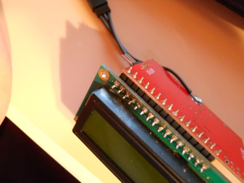
I was too lazy to remove the screen, and managed to remove the shunt without that step.
Still took a while though...
Still took a while though...
The high current shunt works through a simple but elegant application of Ohm's Law. It has exactly 1/1000 (0.001) ohm of resistance. As a result, every 1/1000 (0.001) volt drop across its length equals 1 amp of current. The best part is that the shunt is ridiculously easy to make yourself. Simply solder a Mueller #27 alligator clip to each end of a piece of #8 stranded copper wire. But be very careful about the following three specifics. First, the wire must be #8 stranded copper, available at any home improvement center, and the Mueller #27 alligator clips must be carefully soldered so that the solder does not wick up the wire. This is critical, as it affects the tool’s resistance and therefore its accuracy. Finally, the shunt’s length from clip to clip (not end to end) must be exactly 6 5/8". This is important, as an error of only a quarter inch will throw off the tool’s readability. Coil the shunt after it is assembled to make it more compact.
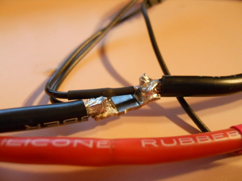
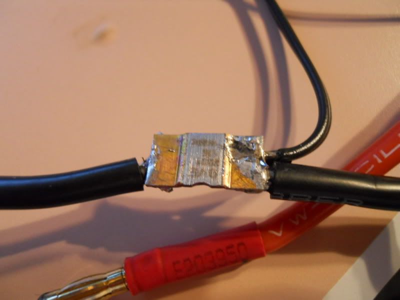
SamTexas said:Instead of relocating the shunt, how about replacing it with an external one? Removing the shunt appears to be quite time consuming. The external shunt can just be a 6 5/8" long of #8 stranded copper. Just a thought.
http://www.motorcycleproject.com/motorcycle/text/shunt.html
The high current shunt works through a simple but elegant application of Ohm's Law. It has exactly 1/1000 (0.001) ohm of resistance. As a result, every 1/1000 (0.001) volt drop across its length equals 1 amp of current. The best part is that the shunt is ridiculously easy to make yourself. Simply solder a Mueller #27 alligator clip to each end of a piece of #8 stranded copper wire. But be very careful about the following three specifics. First, the wire must be #8 stranded copper, available at any home improvement center, and the Mueller #27 alligator clips must be carefully soldered so that the solder does not wick up the wire. This is critical, as it affects the tool’s resistance and therefore its accuracy. Finally, the shunt’s length from clip to clip (not end to end) must be exactly 6 5/8". This is important, as an error of only a quarter inch will throw off the tool’s readability. Coil the shunt after it is assembled to make it more compact.
Sam
Jeremy Harris said:SamTexas said:Removing the shunt appears to be quite time consuming.
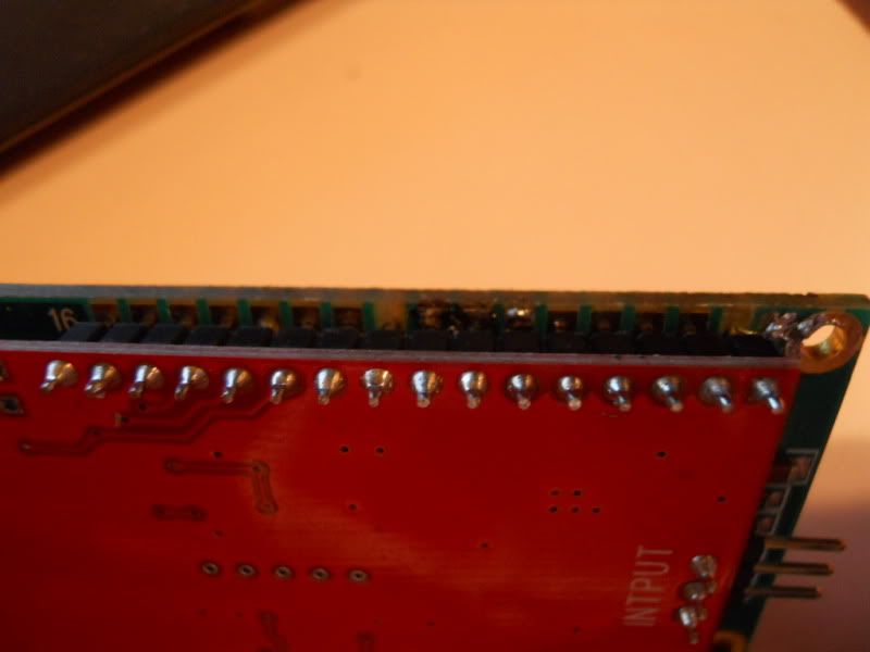
Getting the shunt off the circuit board isn't that hard to do, anyway. I took the display board off to get easier access, but as others have shown that isn't really needed.
Jeremy Harris said:Using copper wire as a shunt is an incredibly bad idea. The reason has to do with the very low resistance of the shunt, 0.001 ohms in this case, and the way that copper wire resistance changes markedly with temperature. Add in that it is very difficult to measure resistances this low and the whole concept of a DIY copper wire shunt that is in any way usably accurate is pretty flawed. The shunts used in these really cheap meters are made from Constantan, and alloy with a very low resistance temperature coefficient. The resistance tolerance of the standard shunt is 1%, much better than you could hope to make with a bit of wire cut to length.
As an example, to get 0.001 ohms requires wire of an exactly known resistance per unit length. This varies markedly from one manufacturer, or even batch, of wire to another, certainly 8g wire can be anything from around 0.0006 to 0.0007 ohms per foot at 20 deg C, so you're starting off with an in-built error of up to around 15%, at a constant temperature of 20 deg C.
Now, add in the effect of temperature error, which will increase the resistance of a bit of copper wire by just over 5% for a change of just 15 deg C, from 20 deg C to 35 deg C, and you get total errors with the copper wire shunt system suggested of around 20% or so. If the wire temperature varies by more than 15 deg C, then the errors will be greater. This sort of error is unacceptably large, particularly when it impacts so massively on the cumulative Ah reading on the meter.
Jeremy
adrian_sm said:Getting the shunt off was actually pretty quick. I did it without removing the display. Most of my time was spent on all the new wiring, termination, heatshrinking etc. Things you would have to do no matter what shunt you use.
To get the shunt out I just let my soldering iron pick up most of the excess solder around each pad, took a couple of goes for each pad. Then sort of pushed the shunt sideways with the soldering iron, first from the left, then right, then left, etc. This let the heat melt the solder between the shunt and PCB on each side, until it was free to move. Done.
- Adrian


jmmorgan said:Mark:
I tried switching the leads, but that did not work. Does anyone have a schematic of the circuit to help me trouble shoot the meter.
Thanks
John

") I was messing around with it and the battery lead shorted out on the screen. It made a nice healthy pop.
I was messing around with it and the battery lead shorted out on the screen. It made a nice healthy pop. 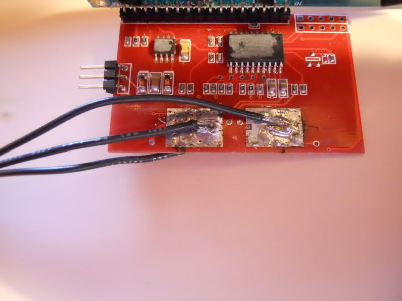
 Sorry I ruined the meter lol Playing with the old one it seems like bending the boards apart doesn't do too much damage. It took me 4-5 90* bends to damage/break a few pins. I'll probably end up bending it just a little if I need to get my iron in there. Perfect!