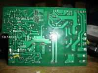
Noob needs help with Headway 24V20ah pack

Depends on the BMS - there should be a dedicated charge cable. If you still want the battery protected, you could use the output after the BMS to trigger a relay in series with the motor, so if your cells hit LVC it disconnects the output.
 
I also tried connecting the old SLA battery (which is almost completely discharged) to the charger, but no luck. The light stayed green and never changed to red. Does anyone have any thoughts on what I should do next re: troubleshooting the charger? I'm still waiting for a response from Michelle at Headway.
 
I wouldn't hold your breath waiting for Michelle.

I'd start using the 24v sla charger and order
http://stores.headway-headquarters.com/-strse-81/24v3a-lifepo4-charger%2C-lifepo4/Detail.bok?category=CHARGERS
or


It sucks, but unless you can diagnosis the charger and repair it.
Have adjusted any of the pots on the charger?
Perhaps it was never setup out of the factory?
 
Isn't the same thing we hear about Michelle at headway as soon as they get your money no help on the bad bms's and charger's that seam to be a problem on a good cell for a good battery on paper. Is it true about headway cells being hard to keep in balance in large battery packs ? Just from what I read over time.
 
Yes, Michelle was very responsive while I was ordering the battery, but as soon as I had a problem the communication stopped. I got one message saying that she'd pass the problem on to her engineer, but I haven't heard anything since, even after numerous follow-ups from me. Needless to say, I'm very disappointed.

Auraslip, thanks for the tip on adjusting the pots. This had a positive effect and the green light switched to red! The first pot I adjusted was the one in the the upper left corner of the picture, near the LEDs. This pot changed the output voltage. I left it at 28.7, even though the case is marked at 29.2. Maybe I'll go back and adjust this later. I was unable to figure out the function of the other two pots but adjusting the middle one (in the picture it's the one that's vertically aligned, next to the fan leads) was what made the difference. As I adjusted it I saw the light switch from green to red and the fan kicked on. I disconnected the battery and the light switched back to green. So the charger appears to be working properly now.

I'd really like to find out what the other two pots do, but for now I'm going to keep a close eye on the charger and make sure it switches back to green when it's finished and that the battery is charged.
 
As for the voltage at charge I would also check the cells for volted level or balance. Sorry to hear she is only interested in your money. Great filling to have things working Good luck. Thanks for the thread.
 
I still haven't been able to get my charger working properly. After finding the adjustment pot that changed the green LED to red, I hoped that charger was working and current was flowing to the battery. To determine this, I ordered a watt meter which arrived yesterday. I hooked it up, with the output of the charger as the power source and the battery as the power load, but the meter read 0.0A and the amp-hour counter remained at zero. I tried to take a picture, but the flash from the camera washed out the meter readings. Anyway, I'm pretty sure current isn't flowing to the battery.

I also noticed another issue with the charger. The voltage at the outputs is stuck at 27.3V and won't go any higher. On the charger case it's marked at 29.2V but even after adjusting the voltage adjustment pot, it doesn't go any higher. If I turn the pot down, the voltage does go down accordingly, but it seems as if 27.3V is its maximum.

Can anyone help diagnose what's wrong with this charger?
 
There is a small amount of current going to the battery. I'd guess this to be a trickle charge. It's been on the charger for 8 hours now and the watt meter reads 0.6ah into the battery.
 
why do you think there is something wrong with the charger? it is new isn't it? did it come with the battery or did you buy it separate from the headway pack?

are you measuring the charger voltage while it is plugged into the pack? what are the cell voltages? do you know where in the charger circuit the pots are located that you were adjusting differently from the factory settings?

do you have a voltmeter? can you use the ammeter scale on the voltmeter to determine if there is a shunt current?
 
why do you think there is something wrong with the charger?
I expected to see around 3A current flowing from the charger into the battery when I hooked up the watt meter. This is the output stated on the front of the charger.

it is new isn't it? did it come with the battery or did you buy it separate from the headway pack?
It is new, it did come with the headway pack.

are you measuring the charger voltage while it is plugged into the pack?
I am measuring the charger voltage when it is unplugged from the pack.

what are the cell voltages?
3.22
6.44
9.67
12.90
16.12
19.34
22.6
25.8

do you know where in the charger circuit the pots are located that you were adjusting differently from the factory settings?
Yes. The voltage pot is located next to the leds. There are two other pots, one of which I adjusted. The pot I adjusted is the one in the picture that's orientated horizontally, closest to the bottom.

do you have a voltmeter?
Yes.

can you use the ammeter scale on the voltmeter to determine if there is a shunt current?
I've never done this before.
 
your voltmeter has a current scale on it. there is a low current setting, and then there is a separate spot for the red lead to plug into that allows you to measure up to 10A on another setting on the dial, on most voltmeters anyway.

it looks like all the cells are close, and not too high so the BMS should not be shut off, and they should be taking full charge, so set your voltmeter up so the current flows through the 10A scale and use some alligator clips to hold the ammeter in the charging circuit so you can measure the current coming out of the charger.

reset the pots to the position they were at when you originally 'adjusted' them and see if any current will flow out of the charger.

i have no idea where these pots are in the circuit so i don't know what could have changed, but you want to set it back to the original settings, then see if there is current coming from the charger and going into the pack. usually the fan is a good indication of charging too, but watch for current flowing out of the charger. through the voltmeter.
 
God help you if you've messed with the pots that control the cc/cv and charge termination functions!

You'll need the manual and/or some one that understands how these chargers work to set them to the proper settings.
 
the wire where it says sensor is the output shunt. if you follow the trace connected to the left side in that picture, next to the S then you should find where the current sense feedback returns. the TL494 IC is the controller and you can google the data sheet to find out which legs do what. the 5k pot in the upper right next to the red led will likely set the range of voltages, but i cannot be certain without examining the traces to see what it is connected to. i think the 1k pot next to the 'sensor' may adjust the sensitivity of the current output, and not sure what the other one next to it does.

your chance to teach yourself some electronics.
 
your voltmeter has a current scale on it. there is a low current setting, and then there is a separate spot for the red lead to plug into that allows you to measure up to 10A on another setting on the dial, on most voltmeters anyway.
Thank you for the information. I followed your instructions and read the current coming out of the charger to be 0.10A. At this point, the LED was red and the fan was blowing. I then returned the pots to their original position (I did keep track of how many turns and in which direction I turned them). The LED turned green and the fan shut off. The current reading remained at 0.10A.

the wire where it says sensor is the output shunt. if you follow the trace connected to the left side in that picture, next to the S then you should find where the current sense feedback returns. the TL494 IC is the controller and you can google the data sheet to find out which legs do what. the 5k pot in the upper right next to the red led will likely set the range of voltages, but i cannot be certain without examining the traces to see what it is connected to. i think the 1k pot next to the 'sensor' may adjust the sensitivity of the current output, and not sure what the other one next to it does.
Thanks for this as well, very helpful. I think your thought about the upper-right pot setting the range of voltages is correct. I will look into the rest of your comment and see if I can get some more information from Google about the other two pots. If you'd like to see any other pics of the charger (from different points of view, for example), let me know and I'll post them.

your chance to teach yourself some electronics.
That's what I'm trying to do. :)
 
if you can follow the traces on the pcb board from those pots to the op amp next to it and over to the 494, then you will have an idea of what function they serve.

between the output voltage + and ground there will be a resistor divider which has the middle leg attached either to the op amp or to the 494. that is how the charger knows when it has reached the final voltage and will shut down the input. switching the led and the fan will be done by that op amp i bet, and the transistors may switch the current in the front end with some outputs from the 494, so look for those and look at the data sheet. #1 pin on the 494 is the feedback output as i recall, can't say much more, but you may have just shut it down by adjusting the current shunt feedback too tight.
 
also, those pots will have 3 legs coming out and usually the middle leg is the wiper. the other two legs are the ends of the resistor that the wiper slides up and down to adjust the resistance.

usually, in fact always, the wiper leg is connected to the end leg on one side, the other end leg goes to the voltage source, and the wiper takes the divided voltage over to where it is used.

the reason the wiper leg is soldered to the end leg usually through the trace, is to eliminate the open circuit noise of the wiper when you adjust it, since the wiper could be 'disconnected' physically as it moves down the resistor so tying the wiper to the end keeps that open circuit resistance within the range of the pot, 1k in the example of your horizontal pot next to the shunt.

102 means 10 times 10^2 or 1000 ohms.
 
I have attempted to follow the traces on the pcb board as indicated. I removed the board from the case and examined it from the front and the back.

For the horizontal pot, it is connected to the Sensor on one end and to pin 2 of the op amp on the other. The op amp is a Hitachi HA17358. The data sheet for the Hitachi is here: http://www.datasheetcatalog.org/datasheet/HitachiSemiconductor/mXqyszx.pdf The pins are:

1 Vout 1
2 Vin- 1
3 Vin+ 1
4 GND
5 Vin+ 2
6 Vin- 2
7 Vout 2
8 Vcc

For the vertical pot, it is connected to the sensor on one end, then a resistor, then to pins 13 and 14 of the 494. The data sheet for the 494 is here: http://focus.ti.com/lit/ds/symlink/tl494.pdf The pins are:

1 1in +
2 1in -
3 FEEDBACK
4 DTC
5 CT
6 RT
7 GND
8 C1
9 E1
10 E2
11 C2
12 Vcc
13 OUTPUT CTRL
14 REF
15 2in +
16 2in -

Here's an annotated pic of the underside of the pcb:

DSCI0262_annotated_800.jpg
 
Back
Top