• Howdy! we're looking for donations to finish custom knowledgebase software for this forum. Please see our Funding drive thread

On-off switch requirements

Garrick_s

100 W
Joined
Oct 13, 2010
Messages
109
Location
Ventura CA
Hello all,
I want to get a better "on/off" switch than what was supplied in the kit.
I see some at radio shack and such, but I'm not sure what requirements need to be met with what ever switch I choose :oops:

Right now the bike is 48V / 10ah.
Considering bumping up to 72 volt soon.
so I want the switch to be able to handle the high voltage too.

Basic two pull - on/off.

Right now its a typical toggle
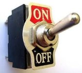
on_off switch_current.jpg

An illuminated rocker would be cool but not mandatory.

SO - what are the basics I need to look for in a switch?
AMP requirements? VOLT requirements?

Thanks for helping a rookie. :D
 
Are we talking battery disconnect switch?

I've used these:

http://www.amazon.com/US-General-Ba...2?s=automotive&ie=UTF8&qid=1291849837&sr=1-12

they're big and designed more robustly than the typically switches you get from radio shack and stuff.

Some controllers so have a kind of "enable" switch which should theoretically draw smaller current.

I've used a 20 amp automotive switch for battery disconnect. The problem is that controllers usually have larger capacitors and so you get this pretty big arc across the switch or contact when you power up. This wears out switches and connectors over time. The 20 amp automotive switches can work ok for a little while but then they fail to short or open. The big disconnect switches with the red key is more robust and should take a long time to fail.
 
What switch you want depends also on what you want it to do. If you want it to be able to cut power in an emergency, when the motor or controller is shorted out and sucking heavy current from the battery, then a regular switch may not work becuase it might just weld shut. :( In those cases, circuit breakers (or contactors) designed for DC at the volts and amps you'd expect at maximum from your system would be better, and probably best to have separate from the switch itself.

One thing you can do easily to limit the damage that happens to switches over time from the charge-up inrush currents when turning your system on, is to add a second parallel switch, much much smaller, that has a resistor in series with it called a precharge resistor. You use one with a value that allows the caps to mostly charge up within some reasonable amount of time (10 to 30 seconds, for instance) but does not allow so much current that the switch's contacts are overwhelmed. A pushbutton can be used if you like, instead of a toggle or rocker, or you can just use a three-position toggle, with precharge first, then full on (bypassing the resistor). Lots of ways of doing precharge.

The main power switch, either way you do it, still needs to be able to handle the maximum amps at the maximum voltage in *DC* (not AC) that you will put thru it. Many switches are only rated for AC, and you will find in general that the ones rated for both are much higher AC ratings than DC ones, but you must go by the DC ratings if you want the switch to last and to properly and safely be able to cut power. :)
 
Garrick,

I you have a brushless motor, then the controller typically has a low current positive wire that supplies power to the brain of the controller. That's where your on off switch goes and is well under a 1A draw, so switch requirements are minimal. I suggest a key switch.

Big heavy kill switches are a carryover from brushless motors, because a short or controller failure can result in a runaway condition. A brushless motor cannot run without power to the brain of the controller, so only a proper fuse is needed on the main power cables close to the battery, not a switch. The switch on the low current controller power wire should be within easy reach, so you can turn it off easily if you have a throttle failure or short, which is the only cause of a runaway condition I can think of. This enables you to have your on/off switch up on the handle bars in easy reach in an emergency.

Switching this way is also better for your controller, because unless you disconnect the battery, the controller's power capacitors stay charged. If you switch the main power, then the inrush of current will wear on the switch itself as well as the caps, without a precharge resistor like AW mentioned to stop the snap/spark.

John
 
Thank you all for your input.
big helps indeed.

It all makes sense as to why, when I flipped the switch to turn it off yesterday, it would not turn off.
All that current from the caps welded my switch "open".......I think.

I did take a look at switches at radio shack last night and noticed that the amp rating changed with the voltage.
12V - 50A, 24V - 20A etc.
I picked up the 12V/50A switch and will use it as a temp so I can ride, but will redo properly when I do the complete re-wire.

I went over to harbor freight (my toy store) and picked up a battery kill switch just like what jondoh called out, but that thing is HUGE.
not sure where I will fit that thing.

Thanks again

G
 
Garrick_s said:
I went over to harbor freight (my toy store) and picked up a battery kill switch just like what jondoh called out, but that thing is HUGE.
not sure where I will fit that thing.

Thanks again

G

Put it right in the middle of your saddle, so when your bike runs away again, and you get anxious and your butt cheeks squeeze in, it'll activate the kill switch :mrgreen: .

(sorry, couldn't resist)

BTW, on a more serious note, your switch was stuck "closed," not "open."

Cameron
 
Garrick_s said:
I went over to harbor freight (my toy store) and picked up a battery kill switch just like what jondoh called out, but that thing is HUGE. not sure where I will fit that thing.
Thanks again
G

Fit it back in the bag. Hang on to the receipt and exchange it for a proper fuse next time you go to your "toy store", because it's unnecessary with your BMC brushless motor. You only need a switch on the low current supply circuit that runs the controller, not the main power wires.
 
some say i need precharge resistor for my lipo 24s set up and i only use a breaker and even the breaker i don't know the rating :D :D to open and kill de current but
can soeme tell what i need to purchase to not damage my controller i will appreciate :D :D :D
 
If you really want to kill a high voltage circuit, go to the autoparts store, buy a $9 ford starter relay, hook it into the circuit to be killed, and then use any switch you want on the trigger side of the relay. Cheap, easy, and can handle enough amps to start a V8. No bigger than a couple packs of ciggarettes, and can go in the battery bag, or mount to the frame, and use rubber covers for the terminals.
Brian L.
 
RallySTX said:
If you really want to kill a high voltage circuit, go to the autoparts store, buy a $9 ford starter relay, hook it into the circuit to be killed, and then use any switch you want on the trigger side of the relay. Cheap, easy, and can handle enough amps to start a V8. No bigger than a couple packs of ciggarettes, and can go in the battery bag, or mount to the frame, and use rubber covers for the terminals.
Brian L.

I'd be a bit careful there. It depends which "starter relay" you mean. Normally the device that is a separate relay doesn't switch the starter current. It just switches the current to the big solenoid on the side of the starter motor and that switches the motor current. Its only very old vehicles that have a separate relay for the motor current.

That's apart from the fact that its for a 12 V system, not a high voltage one.

Nick
 
If you only want to put your controller in standby mode so that it's on but doesn't provide power to the motor, you can splice any low power on/off switch in parallel with one of the brake switches, so that the controller thinks that the brake is applied and therefore cuts the power until you operate the switch again.
 
i already have breaker and for now its work but i have on the controller a on/off switch , my question is if let the breaker on but close
the on/off switch of the controller and then re open it what gonna happen ? by doing this can I protect my capacitor from a surge ?
 
Sorry, Tiberius is correct. I was too eager to help out. The relay I was thinking isn't meant for long duty cycles, as in the length of an ebike ride. And he's right again about the voltage level issue too. Again I apologise.
Brian L.
 
d8veh said:
If you only want to put your controller in standby mode so that it's on but doesn't provide power to the motor, you can splice any low power on/off switch in parallel with one of the brake switches, so that the controller thinks that the brake is applied and therefore cuts the power until you operate the switch again.

I believe you mean in series, because if it''s in parallel, if either switch is closed, the circuit is complete, and the other switch is irrelevant.

Cameron
 
Depends on how the brake switch is designed on that particular one. If it requires a short to activate the brake then parallel is correct, if it requires an open to activate it, then series is correct. :)
 
The brake cut-off doesn't turn the controller off, so a switch there is begging for a dead battery at some point due to the controller being on. A small switch goes on the low current positive wire on the controller that is there specifically for a switch. Putting the switch there keeps the caps charged too, so that's not an issue. Then you're left with needing a precharge resistor only if you've disconnected your battery. I do that only a few times a year, so I just use a heavy resistor and slowly charge the caps manually before completing the battery connection. Going this route eliminates a point of failure that will occur with a switch on the mains unless you get a relatively expensive and unnecessary contactor, so why bother with it? A big mains cutoff switch is only needed on a brushed motor. An appropriately sized fuse is all that is needed on the battery main, and a switch doesn't replace that.

John
 
Rather than start a new thread, this seems a likely place to consolidate some info I was hoping someone else would get answered...

I get the "big spark" when I plug in my 6S liPo through Deans connectors to the ESC power wires. From what I've read, the spark is from the capacitors charging up.

Since batteries get hooked up to chargers, and also get replaced or 'added to' in parallel on occasion, I want the battery-to-[female]connector length to be clean, simple and short. But, somewhere between the connector and the ESC, I would like to have a:

Fuse
On/off switch
Resistor and button to pre-charge capacitors before turning on the master power switch.

I am unsure of the 'best' order in which to chain them together (should all, or just 'some' of the items be on the positive/red wire?). I just now drew a diagram as to my best 'guess', and I am hopeful that someone with some experience can guide me as to the best layout and possibly a short list of selection criteria for the various components, for when a future reader/lurker has a system of various volts and amps:
 
spinningmagnets said:
Rather than start a new thread, this seems a likely place to consolidate some info I was hoping someone else would get answered...

I get the "big spark" when I plug in my 6S liPo through Deans connectors to the ESC power wires. From what I've read, the spark is from the capacitors charging up.

Since batteries get hooked up to chargers, and also get replaced or 'added to' in parallel on occasion, I want the battery-to-[female]connector length to be clean, simple and short. But, somewhere between the connector and the ESC, I would like to have a:

Fuse
On/off switch
Resistor and button to pre-charge capacitors before turning on the master power switch.

I am unsure of the 'best' order in which to chain them together (should all, or just 'some' of the items be on the positive/red wire?). I just now drew a diagram as to my best 'guess', and I am hopeful that someone with some experience can guide me as to the best layout and possibly a short list of selection criteria for the various components, for when a future reader/lurker has a system of various volts and amps:

You don't really need that first switch in series with your resistor, once you flip the second it'll take over and the path with the resistor will just carry some of th ecurrent. Just be sure you get a large enough resistor that it won't get too hot.

Cameron
 
oldpiper said:
You don't really need that first switch in series with your resistor, once you flip the second it'll take over and the path with the resistor will just carry some of th ecurrent. Just be sure you get a large enough resistor that it won't get too hot.

Cameron

The push button in series with the resistor is the capacitor pre-charge switch, which is made for a couple of seconds before switching the main power switch below it.

This is a very good set up, as the capacitor initial charging surge current (which can be hundreds of amps) will be reduced by the resistor, with the result that neither the push button nor the main power switch will see extremely high current.

I made the mistake on my first bike (which had a 15A controller) of just using a single 20A switch as the main power switch, with no pre-charge system. The switch lasted a month or so before the contacts welded closed from the surge current on switch on. The switch was then useless, as the bike stayed on unless I unplugged the battery.

My current bike uses a keyswitch to operate the precharge circuit, with power from this keyswitch also feeding the controller low current feed and my "fuel gauge". My main power switch is a Deans plug used as a shorting link. It never sparks when I plug it in as the pre-charge switch makes sure that the controller capacitors are all charged up first.

Putting the fuse ahead of the switches makes sense too, as that way it protects as much of the wiring as possible.

Jeremy
 
Jeremy,

Is your keyswitch a 2 position switch? The ignition switch I use has 2 positions, though I only have one wired up to the controller power. It seems like a great way to include a precharge resistor on the first position for the RC pack build in the works, which will require a frequent disconnect of the batts. If yours is just a single circuit switch, how do you get around the issue of possibly having a throttle position other than 0 when you connect your Deans plug? Other than my brushed Kelly, none of my controllers have hi-throttle protection at power up. Is that a programming item I missed on these commonly programmable boards?

After one incident, I never turn my key on until I'm sitting on the bike and one hand on the handlebar. Too bad no video of that one incident. Catching a heavy ebike held by one hand on the handlebar while it was turned on at WOT had to be quite a site. :mrgreen:

John
 
I was pondering this very issue just this week.

One question I had, is that I understand using a precharge arrangement will stop the arc in the switch, but doesn't the switch (even where no arc has occured) still need to be sufficiently Amp rated to deal with the amps being used? It is nearly impossible to find a switch that is rated to more than 20 Amps, so if you are running a 40 Amp controller, even if your switch is saved from experiencing an arc, if it is only half rated for the amps being used, won't this mean the switch will still be seing the 40 amps, and hence over time really wear the switch contacts? Much like the wear the guys running 45Amp Andersons see who are running high amp setups?

One solution I saw to this was to use a double pole single throw switch (which was 20amp rated on each side), and double up the wire on each of the poles (so it is effectively 40 amp rated). I had this arrangement put on my BMC 40 amp 48 volt setup by Ellectroride, and the switch worked flawlessly.

On my latest build I have made the same mistake Jeremy mentioned re his 15 amp controller/20amp switch in that I took a racing car key kill switch rated to 100 Amps, thinking that would be more than enough for my 84 volt 40 amp x5 setup, and within weeks it just soldered the switch shut from the arc.

I think the reason the double poll single throw switch worked on my BMC is that it was only 48V. The arc on my 84v setup is just too much.

So my question again is, if the precharge arrangement is used, does the main switch have to be amp rated over the amps used?

Just to be clear, John in CR seemed to be answering the switch issue from a perspective of safety (ie to stop throttle issues on startup). For me it is that i keep all my batteries in a locked box, so i want to be able to switch off at the shops/parking lot without having to disconnect and reconnect my battery every time (and get the arc), so people can't throw the throttle whilst parked. I initially put a switch on the low current wire (the thin positive) for this purpose, but i understand that is still draining the battery technically, as the circuit is still complete on the main wires.

Cheers, Phil.
 
Jeremy, in case I was misunderstood, I did not mean to leave the path with the resistor out, just that if you wired that path in w/o switch, at the first connection the resistor would limit the current, preventing the spark, and then closing the (now only) switch would bypass that part, allowing full current from the battery. Of course, now thinking about it further, making the whole assembly a (2-position plus "off") keyswitch or the like, so you remember to turn it off, would eliminate the need to disconnect the cable for charging the batts. Or, let's automate it, put a high amp relay in the high-current path which would kick in when the caps were charged to engage full power.

Cameron
 
John in CR said:
Jeremy,

Is your keyswitch a 2 position switch? The ignition switch I use has 2 positions, though I only have one wired up to the controller power. It seems like a great way to include a precharge resistor on the first position for the RC pack build in the works, which will require a frequent disconnect of the batts. If yours is just a single circuit switch, how do you get around the issue of possibly having a throttle position other than 0 when you connect your Deans plug? Other than my brushed Kelly, none of my controllers have hi-throttle protection at power up. Is that a programming item I missed on these commonly programmable boards?

After one incident, I never turn my key on until I'm sitting on the bike and one hand on the handlebar. Too bad no video of that one incident. Catching a heavy ebike held by one hand on the handlebar while it was turned on at WOT had to be quite a site. :mrgreen:

John

My key switch is just a simple on-off one, rated at about an amp. It just turns on the pre-charge and the controller electronics, not the main supply to the FETs. The controller has two power leads, as quite a few do.

The XieChang controllers have protection from the throttle being open during power on, they don't start up unless the throttle is closed first. If I were to turn the key on, then hold the throttle open and then put in the shorting link then the bike would take off, I think. In practice, I turn the keyswitch on, then insert the link within a few seconds of each other, whilst leaning over the back of the bike without touching the bars. I also have a handlebar controller on/off switch, that just turns off the controller low power feed. This is usually off unless I'm ready to ride.

Jeremy
 
Definitely worth having a separate switch for the precharge on the contactor. Otherwise, when you turn everything off, the resistor will continue to drain your batteries. Might take 7 days, but a flat battery is guaranteed.
 
Back
Top