You are using an out of date browser. It may not display this or other websites correctly.
You should upgrade or use an alternative browser.
You should upgrade or use an alternative browser.
Rickys High Power Flexable motor controller
- Thread starter Ricky_nz
- Start date
Thud
1 MW
I'll second Arlo's sentiments.
Add me to the list of board hounds. A couple ought to do me when the time comes.
As for worrying about guy's wrecking something, its a "kit" for those with the knowledge to play with. anyone blowing up their stuff should know thats the price of learning this stuff. (I still go back & watch Arlo's video of the 18ffet plasma show at least once a week ) You won't have any complaints from the crew here looking to build on your excelent foundation. Thanks for the start. T
Add me to the list of board hounds. A couple ought to do me when the time comes.
As for worrying about guy's wrecking something, its a "kit" for those with the knowledge to play with. anyone blowing up their stuff should know thats the price of learning this stuff. (I still go back & watch Arlo's video of the 18ffet plasma show at least once a week
And so died a legend! That was a sad day for me! But i will stop at nothing to be one of the first riding a kick ass brushless motorcycle! And ev for that mater!Thud said:I'll second Arlo's sentiments.
(I still go back & watch Arlo's video of the 18ffet plasma show at least once a week) You won't have any complaints from the crew here looking to build on your excelent foundation. Thanks for the start. T
Ricky_nz
10 kW
Hi all,
I just got notice my prototype PCBs for the power stage are shipping today so I guess I will have them Monday or Tuesday NZ time all going well

Probably be next weekend before I get one built up though.
Those FETS I brought are in for a party if I haven't messed anything major up.
Because of that I will be doing some final tests on the control board and writing a bit more software for it this weekend to confirm every IO line works as expected ( I have already tested 90%+ ) so I can decide if I want to order more boards with the current layout. (99.9% likely).
One unfortunate thing about ordering more control boards before more power boards will be the extra shipping charge but I will order enough control board PCBs to make it worth while.
Ricky
I just got notice my prototype PCBs for the power stage are shipping today so I guess I will have them Monday or Tuesday NZ time all going well
Probably be next weekend before I get one built up though.
Those FETS I brought are in for a party
Because of that I will be doing some final tests on the control board and writing a bit more software for it this weekend to confirm every IO line works as expected ( I have already tested 90%+ ) so I can decide if I want to order more boards with the current layout. (99.9% likely).
One unfortunate thing about ordering more control boards before more power boards will be the extra shipping charge but I will order enough control board PCBs to make it worth while.
Ricky
Ricky_nz
10 kW
I have uploaded the analog trip comparator and opamp page of the schematic which is useful to implementers of power boards.
The values are not the final ones. I have changed a few.
The opamps are not necessary for use with my power board, just fit resistors in the feedback positions and invert software gain.
They are only there to allow adapting the board to other uses.
A nice cost saving .
.
http://endless-sphere.com/forums/download/file.php?id=49930
/TRIP0 turns off the PWM outputs under hardware control and is used for the cycle by cycle limiting.
The other trips are hooked up to interrupts and can be used for taking action quickly.
I'm decided not to worry about hysteresis on the comparators as once they trip the micro will take action so they should not sit and oscillate.
Ricky
The values are not the final ones. I have changed a few.
The opamps are not necessary for use with my power board, just fit resistors in the feedback positions and invert software gain.
They are only there to allow adapting the board to other uses.
A nice cost saving
http://endless-sphere.com/forums/download/file.php?id=49930
/TRIP0 turns off the PWM outputs under hardware control and is used for the cycle by cycle limiting.
The other trips are hooked up to interrupts and can be used for taking action quickly.
I'm decided not to worry about hysteresis on the comparators as once they trip the micro will take action so they should not sit and oscillate.
Ricky
Ricky_nz
10 kW
I have started building up a second control board. I will do a third at the same in parallel so I don't have to keep searching for parts etc. Just fitting the fine pitch parts first.
I'm getting better at soldering these tiny chips down. 0.5mm center - center on the pins.
The tip on my iron covers about 3 or 4 pins at a time and I prefer it to a smaller tip for this job :lol:.
Plenty of flux and wick on standby.
A layer of flux from the syringe on the pads first sure helps hold the chip in position until it is tacked down with solder and makes it easier to align.
These chips certainly went on a lot quicker and better with less removal of solder than the first boards ones.
On the first board I tried drag soldering like I use to for PLCC but I'm obversely too heavy handed to do that on these chips (Its too easy to bend pins and damage pads doing that :lol: so 4 pins at a time it is. Doesn't take long to do a 100pin micro at 4 pins at a time as you only need to add more solder to the iron after you have done several groups of pins. I found sitting the iron on the pins then pulling away from the chip slowly once the solder flows seems to work for me .
.
A small 9x magnifier is great for checking after a side has been soldered and even useful when held above the chip and iron while soldering.
The image isn't great fout shows the chips I'm referring to.
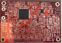
I'm getting better at soldering these tiny chips down. 0.5mm center - center on the pins.
The tip on my iron covers about 3 or 4 pins at a time and I prefer it to a smaller tip for this job :lol:.
Plenty of flux and wick on standby.
A layer of flux from the syringe on the pads first sure helps hold the chip in position until it is tacked down with solder and makes it easier to align.
These chips certainly went on a lot quicker and better with less removal of solder than the first boards ones.
On the first board I tried drag soldering like I use to for PLCC but I'm obversely too heavy handed to do that on these chips (Its too easy to bend pins and damage pads doing that :lol: so 4 pins at a time it is. Doesn't take long to do a 100pin micro at 4 pins at a time as you only need to add more solder to the iron after you have done several groups of pins. I found sitting the iron on the pins then pulling away from the chip slowly once the solder flows seems to work for me
A small 9x magnifier is great for checking after a side has been soldered and even useful when held above the chip and iron while soldering.
The image isn't great fout shows the chips I'm referring to.

grindz145
1 MW
Awesome. If you give me an idea how much a PCB / kit would go for I very well might be in for a couple, and this way you could get a little more volume.
How come you don't order a lazer cut stencil and then just bake all the SOIC parts on with some solderpaste?
How come you don't order a lazer cut stencil and then just bake all the SOIC parts on with some solderpaste?
Ricky_nz
10 kW
I'm working on that, as usual too many things on the go at once.grindz145 said:Awesome. If you give me an idea how much a PCB / kit would go for I very well might be in for a couple, and this way you could get a little more volume.
I need to run a few numbers. Bare boards are going to be quite reasonable I think but I just need a little bit of time on the spreadsheet.
I may be able to work out a bare board cost in the next few days. I will have to investigate shipping costs at some point too.
For a kit or built up I need to decide on the final BOM, like if the opamps are needed. Once I have my power board running it will all firm up. I'm working on a final cleaned up BOM and assembly information for the Rev 1 control boards anyway.
If I leave the opamps off then there is a reasonable saving and the board is usable for most applications but if they are required for a particular application they are easy to add ( soic 8 ).
[/quote]grindz145 said:How come you don't order a lazer cut stencil and then just bake all the SOIC parts on with some solderpaste?
I haven't looked at that yet and not sure of the cost or where to get them. The board still at the prototype stage until I have at least the motor turning so although unlikely there is a tiny chance I may change the layout. It doesn't actually take long to solder by hand but if quantities go High enough I would definitely have to look at stencil etc.
Also wouldn't want to be learning a new process on the first 5 boards :lol:
Ricky
Ricky_nz
10 kW
Hi all,
I've been thinking about pricing for bare control boards (no components fitted).
Its really hard to decide on a price as it depends on quantities I buy in so risk involved etc.
Unfortunately the cost has to take into account the tax man etc.
Provisional pricing bare control boards (no components fitted) NZD $40 (approx USD$30 depending on exchange rate)
Remember the NZD is currently around 0.75 US depending on the randomness of the financial types.
I may be able to offer discounts for multiple boards PM if interested.
Shipping is extra, probably NZ$30 - NZ$40 to US, I need to look into that some more before I actually put them on sale.
It might be a good idea if someone in the US wants to receive a package of boards and distribute them to save on shipping.
I'm open to suggestions here as I know shipping between New Zealand and the US is expensive.
For this you are getting not only the 4 Layer board but the right to use the software I'm developing that will support not just
Hall effect mode but I am targeting full vector control (sinewave) and sensorless operation for mid next year (no guarantees on date).
There will be software updates until I get that fully running and as I improve it.
Initial software will be hall effect sensored trapezium drive of which a simple version will be available when I release the boards.
This first software will be fairly simple but I hope to quickly build up the routines for throttle response etc.
I will be expanding the CAN interface later to allow interaction to dashboards and BMS's and even grouping of motor controllers etc.
The software allows full configuration of the board to scale to your desired voltage and current etc.
Although I will provide software there is nothing stopping you from using your own software on this board,
I will provide sufficient details and at some sample source code for a simple application that can run on the board for those who want to do it themselves.
I will also provide assistance on endless-sphere to get the board / software working in your application.
Minor software customisation as long as its also useful to others is not a problem .
.
Major customisation not applicable to others may have additional cost
To use this board you would need to provide a 15VDC supply and your own gate drive circuits and CT's as per the implementation guide.
Board features:
microsd for data logging and parameter storage
USB interface
TTL serial interface for debugging of configuration
CAN interface
Hardware current trip circuiits
simultaneous sampling ADC for 2 paris of channels.
SPI interface (currently unused)
see http://endless-sphere.com/forums/download/file.php?id=49760 for the IO connections to yuour power board.
I will order more boards shortly provided the pricing doesn't scare too many of you off :lol:
I'm working on a final BOM for this board but its not quite ready yet.
I do have a target price in mind for the built up control boards but until I do the BOM I'm not sure if it is achievable.
Hopefully I'm not too far off the mark on pricing. I'm sure you will let me know if I am.
Ricky
I've been thinking about pricing for bare control boards (no components fitted).
Its really hard to decide on a price as it depends on quantities I buy in so risk involved etc.
Unfortunately the cost has to take into account the tax man etc.
Provisional pricing bare control boards (no components fitted) NZD $40 (approx USD$30 depending on exchange rate)
Remember the NZD is currently around 0.75 US depending on the randomness of the financial types.
I may be able to offer discounts for multiple boards PM if interested.
Shipping is extra, probably NZ$30 - NZ$40 to US, I need to look into that some more before I actually put them on sale.
It might be a good idea if someone in the US wants to receive a package of boards and distribute them to save on shipping.
I'm open to suggestions here as I know shipping between New Zealand and the US is expensive.
For this you are getting not only the 4 Layer board but the right to use the software I'm developing that will support not just
Hall effect mode but I am targeting full vector control (sinewave) and sensorless operation for mid next year (no guarantees on date).
There will be software updates until I get that fully running and as I improve it.
Initial software will be hall effect sensored trapezium drive of which a simple version will be available when I release the boards.
This first software will be fairly simple but I hope to quickly build up the routines for throttle response etc.
I will be expanding the CAN interface later to allow interaction to dashboards and BMS's and even grouping of motor controllers etc.
The software allows full configuration of the board to scale to your desired voltage and current etc.
Although I will provide software there is nothing stopping you from using your own software on this board,
I will provide sufficient details and at some sample source code for a simple application that can run on the board for those who want to do it themselves.
I will also provide assistance on endless-sphere to get the board / software working in your application.
Minor software customisation as long as its also useful to others is not a problem
Major customisation not applicable to others may have additional cost
To use this board you would need to provide a 15VDC supply and your own gate drive circuits and CT's as per the implementation guide.
Board features:
microsd for data logging and parameter storage
USB interface
TTL serial interface for debugging of configuration
CAN interface
Hardware current trip circuiits
simultaneous sampling ADC for 2 paris of channels.
SPI interface (currently unused)
see http://endless-sphere.com/forums/download/file.php?id=49760 for the IO connections to yuour power board.
I will order more boards shortly provided the pricing doesn't scare too many of you off :lol:
I'm working on a final BOM for this board but its not quite ready yet.
I do have a target price in mind for the built up control boards but until I do the BOM I'm not sure if it is achievable.
Hopefully I'm not too far off the mark on pricing. I'm sure you will let me know if I am.
Ricky
Ricky_nz
10 kW
Thanks texaspyro,texaspyro said:$25 bucks a 8.5x11" sheet for high quality Kapton stencils... http://ohararp.com/Stencils.html
Check Sparkfun's tutorials for some stenciling basics.
The stencils don't seem too bad price wise. I will definitely have a read up on Sparkfun when I get a chance.
Ricky_nz
10 kW
In the interests of getting information out there I have attached an early version of the assembly document for the control board. It contains a BOM and a few snippets of the circuit. I will be updating this document over the next few weeks.
It will only be finalised once I have the board working with my power board but its a start.
I haven't added the rotate some of the SO-23 parts info yet as I want that to be a marked up photo.
The parts still line up with the pads so will be robust and reliable.
I have been looking at the cost savings for the parts as can be seen in the document.
Built up boards from me will have the minimum parts but all the necessary protection parts for "standard applications".
This will help keep the cost down as there is currently NZ$10 of opamps that are unnecessary is most applications :lol:.
View attachment RFMC-Control Board Assembly-instructions-brdrev2-docrev-v0.1.pdf
Ricky
Ricky_nz
10 kW
Power Boards are here! 


I measured 307pF between the +Bus and -Bus so not much. I wasn't expecting too much as the two planes only overlap over one section of the board. Still might be useful though.
The only issue I have observed so far is I was not as tidy as I could have been when I put holes in the solder mask for beefing up the tracks. It looks a bit funny in one place where I went off the copper so you see the fibreglass rather than the red solder mask. not a problem but it does look different. The internal planes look ok but I will find out for sure when I start building it up.
One of the electros is a little close to the control board. I forgot I had added a small boarder arround the control board and also that the electros are about 1mm bigger than the footpring(I was too lazy to do a new footprint). This can be solved by mounting the cap on a small angle or using a slightly lower value capacitor in that one position. on the plus side the CTs fit nicely in the plated through slots
With 3 ounce copper in the internal layers and 4 ounce on the outside layers these boards feel heavy, especially when holding all six.
And yes the inter board connector and mounting holes line up perfectly
[youtube]UJ7kwKnjk_E[/youtube]
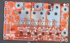
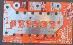
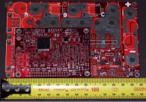
It isn't too big.
Its new in the house so it got the once over :lol:
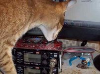
I better buy a new 3mm Tap set this week so I can prep the heatsink for the standoffs and the MOSFET mounting holes.
Ricky
I measured 307pF between the +Bus and -Bus so not much. I wasn't expecting too much as the two planes only overlap over one section of the board. Still might be useful though.
The only issue I have observed so far is I was not as tidy as I could have been when I put holes in the solder mask for beefing up the tracks. It looks a bit funny in one place where I went off the copper so you see the fibreglass rather than the red solder mask. not a problem but it does look different. The internal planes look ok but I will find out for sure when I start building it up.
One of the electros is a little close to the control board. I forgot I had added a small boarder arround the control board and also that the electros are about 1mm bigger than the footpring(I was too lazy to do a new footprint). This can be solved by mounting the cap on a small angle or using a slightly lower value capacitor in that one position. on the plus side the CTs fit nicely in the plated through slots
With 3 ounce copper in the internal layers and 4 ounce on the outside layers these boards feel heavy, especially when holding all six.
And yes the inter board connector and mounting holes line up perfectly
[youtube]UJ7kwKnjk_E[/youtube]


It isn't too big.
Its new in the house so it got the once over :lol:

I better buy a new 3mm Tap set this week so I can prep the heatsink for the standoffs and the MOSFET mounting holes.
Ricky
Ricky_nz
10 kW
I started assembling the board today. just a few of the bigger parts. A bit too tired to do the SMD stuff tonight.
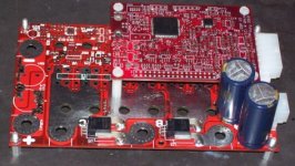
Picture with a partially assembled digital board sitting on standoffs above the power board (the control board is 180 deg rotated from how it should be, just sitting there but when placed on correct way everything lines up ).
Those CT's at the bottom aren't coming out any time soon :lol:. They gave my 80W Hakko a workout to solder in :lol:. Filling in some of the vias linking the planes took a huge of heating. Of course I did not add any thermal relief because It could become a fuse at the currents I intend playing with.
Maybe I need to get one of those vicious soldering irons mentioned in the battery threads for soldering up the heavy stuff on the power board but keep them away from the smd parts :lol:.
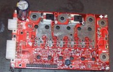
This one shows the solder filled vias for extra current handling. You may think how hard can it be to fill a via with solder.
It took quite a bit of heat as there is 2 or more layers of copper fill (3 ounce or 4ounce each) involved which act as really good heatsinks!
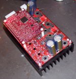
Here is a photo before I soldered anything. I wanted to see how it would look. You can see the small clearance problem with the cap next to the control board. When I soldered the board I bent the legs of this cap and had it sit a few mm higher and offset so It clears the board. since this isn't ideal I will glue it to the adjacent capacitor and to the board if i can find a suitable glue to fill the gap. might want to be a bit stronger than RTV i guess.
I'm not sure whether I should build up the copper on the first board or If I should leave it as it came for a temperature comparison.
It would be difficult to build up the copper areas on the bottom after the MOSFETS are fitted so I might solder some tinned braid from some RG58 coax I conveniently have on a roll here but that would stop me getting a baseline temperature reading at various currents.
The alternative is not to build up the traces on the bottom side of the first board but to instead place a copper bar and pins along the top side soldered onto the MOSFET pads. This would have the advantage that it could be added after the MOSFETS and Baseline temperature tests.
Bonus test: I plugged my first prototype control board in that still has the 15V from an external regulated supply attached and turned it on. The 5V reached the CT's and there were no shorts on the 15V rail so it looks like there are no major problems with the internal layers of the board so far. The CT's added about 20mA to the current draw (total 130mA @ 15V). At 15V in the 5V regulator gets noticeably warm. If you hold your finger on it for a while it becomes uncomfortable so I may want to look at a small heat sink or just solder a small piece of copper onto the devices tag. The regulator is SOT223 so limited heat sinking options. It does run cooler at 13.8V so if the MOSFETS are happy with 13 V gate pulses then I can just lower the buck regulator output voltage on the power board to reduce the linear regulator dissipation.
Interesting discussion with a hardware engineer at work. He recommends I start without the SMD caps as he thinks they may be too good and cause unwanted ringing due to the lack of damping. I will have a bit of testing ahead to determine the best cap combination and gate drive resistance etc but shouldn't take too long when I get there.
I have just ordered some polyprop caps for the leaded positions. Panasonic ones with good pulse handling.
I couldn't get the EPCOS ones I originally wanted and the panasonic ones look good enough in the right footprint and are available now so I see how they go.
Picture with a partially assembled digital board sitting on standoffs above the power board (the control board is 180 deg rotated from how it should be, just sitting there but when placed on correct way everything lines up ).
Those CT's at the bottom aren't coming out any time soon :lol:. They gave my 80W Hakko a workout to solder in :lol:. Filling in some of the vias linking the planes took a huge of heating. Of course I did not add any thermal relief because It could become a fuse at the currents I intend playing with.
Maybe I need to get one of those vicious soldering irons mentioned in the battery threads for soldering up the heavy stuff on the power board but keep them away from the smd parts :lol:.

This one shows the solder filled vias for extra current handling. You may think how hard can it be to fill a via with solder.
It took quite a bit of heat as there is 2 or more layers of copper fill (3 ounce or 4ounce each) involved which act as really good heatsinks!

Here is a photo before I soldered anything. I wanted to see how it would look. You can see the small clearance problem with the cap next to the control board. When I soldered the board I bent the legs of this cap and had it sit a few mm higher and offset so It clears the board. since this isn't ideal I will glue it to the adjacent capacitor and to the board if i can find a suitable glue to fill the gap. might want to be a bit stronger than RTV i guess.

I'm not sure whether I should build up the copper on the first board or If I should leave it as it came for a temperature comparison.
It would be difficult to build up the copper areas on the bottom after the MOSFETS are fitted so I might solder some tinned braid from some RG58 coax I conveniently have on a roll here but that would stop me getting a baseline temperature reading at various currents.
The alternative is not to build up the traces on the bottom side of the first board but to instead place a copper bar and pins along the top side soldered onto the MOSFET pads. This would have the advantage that it could be added after the MOSFETS and Baseline temperature tests.
Bonus test: I plugged my first prototype control board in that still has the 15V from an external regulated supply attached and turned it on. The 5V reached the CT's and there were no shorts on the 15V rail so it looks like there are no major problems with the internal layers of the board so far. The CT's added about 20mA to the current draw (total 130mA @ 15V). At 15V in the 5V regulator gets noticeably warm. If you hold your finger on it for a while it becomes uncomfortable so I may want to look at a small heat sink or just solder a small piece of copper onto the devices tag. The regulator is SOT223 so limited heat sinking options. It does run cooler at 13.8V so if the MOSFETS are happy with 13 V gate pulses then I can just lower the buck regulator output voltage on the power board to reduce the linear regulator dissipation.
Interesting discussion with a hardware engineer at work. He recommends I start without the SMD caps as he thinks they may be too good and cause unwanted ringing due to the lack of damping. I will have a bit of testing ahead to determine the best cap combination and gate drive resistance etc but shouldn't take too long when I get there.
I have just ordered some polyprop caps for the leaded positions. Panasonic ones with good pulse handling.
I couldn't get the EPCOS ones I originally wanted and the panasonic ones look good enough in the right footprint and are available now so I see how they go.
grindz145
1 MW
Ricky you can definitely count me in for a board. I would be willing to do some redistribution in the US if there's enough people interested. The modular design in and of itself will be really nice.
Power board is gorgeous. I'm already thinking about designs for larger versions
Good to hear it is going well!
P.S. Nice ham radio gear...
Power board is gorgeous. I'm already thinking about designs for larger versions
Good to hear it is going well!
P.S. Nice ham radio gear...
CamLight
10 kW
Nicely done Ricky! It's great to see this moving forward.Ricky_nz said:This one shows the solder filled vias for extra current handling. You may think how hard can it be to fill a via with solder.
It took quite a bit of heat as there is 2 or more layers of copper fill (3 ounce or 4ounce each) involved which act as really good heatsinks!
Even though I'm using a 60W OKI SmartTip iron, I've had great luck using a hot plate (Thermolyne 1900), set to 100C-150C, to preheat while soldering my heavier boards. Even when soldering down 8AWG wire leads to a 4-layer 3oz board with loads of thermal vias. Not asking the iron to heat up all that copper really makes a difference!
In fact, lately I've been using the plate, set to 100C, even when just soldering smaller components as it makes things go so much faster. Even the smaller caps can have a few vias to a heavy GND plane and the preheating really helps with that.
No idea how much the plates cost these days (bought mine years ago) but even if it's US$300, it's worth it! I'm sure an inexpensive coffee cup warmer would help too though (can they go to 100C?).
[Edit] LOL...I guess I'm wayyyy out of touch regarding how much the plates cost nowadays. My model does actually cost almost US$300!!
Ricky_nz
10 kW
Thanks CamLightCamLight said:In fact, lately I've been using the plate, set to 100C, even when just soldering smaller components as it makes things go so much faster. Even the smaller caps can have a few vias to a heavy GND plane and the preheating really helps with that.
No idea how much the plates cost these days (bought mine years ago) but even if it's US$300, it's worth it! I'm sure an inexpensive coffee cup warmer would help too though (can they go to 100C?).
[Edit] LOL...I guess I'm wayyyy out of touch regarding how much the plates cost nowadays. My model does actually cost almost US$300!!
I guess I can always run it off my variac if the thermostat doesn't go that low or is too inaccurate.
Ricky_nz
10 kW
Hi grindz145,
Larger power boards would be interesting to see. I think LFP is into large power stages too. Next year should be an interesting year for motor controllers for ebikes etc.
Ok, Il let you know when I'm ready to supply boards etc.grindz145 said:Ricky you can definitely count me in for a board. I would be willing to do some redistribution in the US if there's enough people interested. The modular design in and of itself will be really nice.
Yep it looks the part, not it has to work :lol: . Hopefully I don't run into too many issues. My main concern is the buck converter since its the first time I have used that chip and I used their tool to design the converter. Hopefully it works out ok.grindz145 said:Power board is gorgeous. I'm already thinking about designs for larger versions
Good to hear it is going well!
Larger power boards would be interesting to see. I think LFP is into large power stages too. Next year should be an interesting year for motor controllers for ebikes etc.
Yep I've had those two for quite a while the FT212 2m one I brought when I got my licence and it was just new on the market 1990 ish. I brought the FT712 70CM one later second hand. Great reliable little rigs apart from the their habit of blowing dial lights. I keep planning to open them up and fit some LED's. I haven't been on the air much lately, I really need to put up some decent aerials etc.grindz145 said:P.S. Nice ham radio gear...
boostjuice
10 kW
Arghh! careful of ESD from that cat! 

Great work Ricky. Add me to the list. Let me know if you need help with component population.
Great work Ricky. Add me to the list. Let me know if you need help with component population.
liveforphysics
100 TW
Rickys cat always wears an anti-static collar when doing board inspections. 
Ricky_nz
10 kW
boostjuice said:Arghh! careful of ESD from that cat!
Great work Ricky. Add me to the list. Let me know if you need help with component population.
I'm trying to train the cat Leica to stay off my workbench/static mat but its not always successful although she seems to be realising when I'm working there it isn't a good time to leap up. The computer desk is another story. She thinks she makes the perfect window :lol:.
She was easier to teach to fetch than to keep of benches.
I think when I'm building boards to sell I will have to shut her outside to be on the safe side.
I'll see how things go with the board and let you know about component population.
It depends on how many built up ones are needed I can manage a few but if too many people want them in a short space of time I will definitely look at getting you involved in building some
I am hoping I'll be able to make the final decision about ordering more board blanks soon and then I see what happens.
I have most the parts I need to build up several power boards for testing and I want to do that before i do much more with the control boards. Just waiting on a couple of parts from digikey. Seems to have been sitting in aussie all of today... I guess they will be here Monday.
Unfortunately the parts stuck in aussie are the leaded caps that I want to put across the DC bus so I'll just have to do initial tests and get a feel for things without them and see how well the SMD ones do.
I have enough parts to start playing with the gate drive so that will be this weekends project.
I want to see this thing push some current around :lol:.
I better video it in case there are some fireworks. There shouldn't be though with initial tests being on a regulated supply although if all goes well I will ramp up the output current of at least one phase into an inductive load with similar inductance to the motor at a very low output voltage.
If I make good progress on the gate drive I will finish building up a control board with the minimum part set to confirm its good to go and then I could order more blank control boards.
Been talking to some mates about motor control and are starting to think about the possible methods to make sensorless work well with the turnigy. I will still get hall effect based running first on my GM hub but I really want to run the big turnigys on sinewaves sensorless :lol:.
I like a challenge but they have a lot of saliency (cogging) giving inductance change based on rotor position so sensor-less should work well). Once above some minimum speed I should be able to switch over to the calculated BEMF method. Of course the focus will need to be on the start up from zero part.
I also need to drill and tap the heat sink for the first power stage sometime this weekend.
I have a new 3mm tap set (includes 2.5mm drill bit) so hopefully I don't break a tap.
Its a mechanical engineering thing so I'll probably mess that part up :lol:. Tips are welcome.
I have got a drill press for drilling the holes so I should at least get that right.
Ricky.
Ricky_nz
10 kW
Track Beefing up
The board already has a lot of copper in it but a few calculations suggest that it clooudl be stressed at currents I intend to try and run and since I didn't fancy trying to beef up tracks with the MOSFETS in place I did it now.
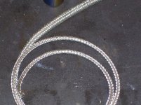
I used the braid from RG58C/U. much cheaper than other sources of braid I found locally and I happen to have 90 odd meters sitting on a roll here (The joys of ham radio) This wimpy 1/4" coax is only good for patch leads and short aerial runs but its braid in tinned and there is no grease in the cable so really perfect for harvesting the braid from .
.
 .
.
Beefing up the tracks went easier than my first go at filling vias etc. I have found my bigger tip for my iron so it was much more efficient at getting its 80W into the board .
.
Nothing stopping me fitting MOSFETS now. I will leave the top side phase outputs without braid so I can get some idea of the heating involved as they are the worst as they only have one layer of 4 ounce copper. They can be easially beefed up after assembly anyway.
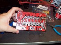
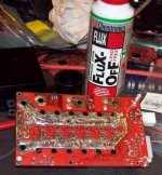
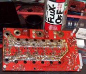
Both the +Bus and -Bus have 3 runs of braid flattened and soldered over most of their area.
If the 3 ounce and 4 ounce coipper wasen't enough this will cover it i think.
If the board runs cool maybe I'll use less on the next board.
I'm sure someone was having a laugh when they designed the label on the flux remover :lol:
Time to go wash my hands and get something to eat. (Leaded solder and flux probably aren't good salt substitutes :lol:
The board already has a lot of copper in it but a few calculations suggest that it clooudl be stressed at currents I intend to try and run and since I didn't fancy trying to beef up tracks with the MOSFETS in place I did it now.
I used the braid from RG58C/U. much cheaper than other sources of braid I found locally and I happen to have 90 odd meters sitting on a roll here (The joys of ham radio) This wimpy 1/4" coax is only good for patch leads and short aerial runs but its braid in tinned and there is no grease in the cable so really perfect for harvesting the braid from
 .
.Beefing up the tracks went easier than my first go at filling vias etc. I have found my bigger tip for my iron so it was much more efficient at getting its 80W into the board
Nothing stopping me fitting MOSFETS now. I will leave the top side phase outputs without braid so I can get some idea of the heating involved as they are the worst as they only have one layer of 4 ounce copper. They can be easially beefed up after assembly anyway.


Both the +Bus and -Bus have 3 runs of braid flattened and soldered over most of their area.
If the 3 ounce and 4 ounce coipper wasen't enough this will cover it i think.
If the board runs cool maybe I'll use less on the next board.
I'm sure someone was having a laugh when they designed the label on the flux remover :lol:
Time to go wash my hands and get something to eat. (Leaded solder and flux probably aren't good salt substitutes :lol:
grindz145
1 MW
Good luck with the mechanical part. It's never my favorite either Traces look pretty beefy though, certainly looks reminiscent of my 18FET 100A beasty. What is the copper thickness on the board?
P.S. Feedline, it's not just for radios anymore. Did you pull out the center conductor and insulator then? That must have been fun... 8)
P.S. Feedline, it's not just for radios anymore. Did you pull out the center conductor and insulator then? That must have been fun... 8)
Ricky_nz
10 kW
The board is 104um / 3 ounce on internal layers and the external layers are 140um / 4 ounce.grindz145 said:Good luck with the mechanical part. It's never my favorite eitherTraces look pretty beefy though, certainly looks reminiscent of my 18FET 100A beasty. What is the copper thickness on the board?
The board was also hot air solder levelled rather than tin plated which I'm sure made the beefing up process easier.
the -ve bus is bigger internally and overlaps the +bus to gain area and reduce resistance, also give 305pf of capacitance.
The +bus is the same size on the outside layer as the internal one.
The phase output areas on the top side do not have any internal parts so they are only 140um/4ounce but will be easy to improve after I have assessed the heating situation.
Yep, I removed the centre+insulator, its actually quite easygrindz145 said:P.S. Feedline, it's not just for radios anymore. Did you pull out the center conductor and insulator then? That must have been fun... 8)
1) first I remove the outer jacket with the aid of a knife
2) bunch up the braid slightly by compressing it lengthways
3) slide out centre and insulator (no force required)
4) pull removed braid back lengthwise until its the size you want then flatten it.
The above took less than 1 minute to get about a meter of braid
The centre insulator on all RG58 I've seen is quite slippery so slides easily.
You can do the same to RG213 (1/2" coax) if you want bigger braid.
Similar threads
- Replies
- 0
- Views
- 124
- Replies
- 24
- Views
- 1,963
- Replies
- 11
- Views
- 1,842
- Replies
- 63
- Views
- 7,196
- Replies
- 20
- Views
- 2,940

