Swedish Kona DH Cromotor 10kW Kelly *Water cooling?*

John in CR said:
knighty said:
you can fit them pointing in opposite directions on each side, so one side sucks and the other side blows

and/or, google a vented brake disk... you could use somehting like that for the 'out' side if you have enough room... so you could push air in at the outside edge with the blades, and then suck it out from the center of the opposite side ?

Impossible. No fan on the planet works like that, because air won't fight against centrifugal force.

Yup, youd need an unbalanced force applied to the air to make it move in a linear form. matching of forces will cause circulation not venting.
 
John, I´m afraid that with the holes milled sideways as I have them now, the blades will not be able to protrude the cover.
I plan to mill the slot maybe 2-3 times wider, so I might be able to get a narrower piece down in the hole, and have it wider on the outside.

Should I try to shield the outer diameter, as I did with my cardboard template? So that air cannot rush in from the perimeter?

IMG_00381_zps6119bbf2.jpg


I got my hands on a student version of Solidworks yesterday, complete with the flow simulation part :lol:

If I could just learn to work it, I could really see the difference between an angle here, or a bend there...
Think I need to watch some tutorials on Youtube today...


hillzofvalp said:
You have got to convert your E30 to electric someday! Cheers :mrgreen:

Ohhh don´t I know it Sir! :mrgreen:

This particular one will not become subject for electric conversion, but I dream wet dreams of a E30 station wagon all electric... Mmmm... *drool*
 
http://www.dyson.com/fans/browsetherange.aspx?filters=table
2009-11-05-b.jpg

or the Chinese copy : iFAN
http://www.ebay.com/itm/LAVA-AIRE-I...733?pt=LH_DefaultDomain_0&hash=item27c754d3a5

I can have a second hand one for 40$ but a 12inch model...if they once make a 8 inch model would be the future or someone need to do a full blower Kit...

check on grabcad for exemple files...(blower/impeler/fan/turbine...many files if you got acess to a 3D print,
medium.png

http://grabcad.com/library/turbine-test-part
imagine the full large part is the hub and check holes placement...I think top or right side is the entry of the turbine...
 
Peter Sternersson said:
John, I´m afraid that with the holes milled sideways as I have them now, the blades will not be able to protrude the cover.
I plan to mill the slot maybe 2-3 times wider, so I might be able to get a narrower piece down in the hole, and have it wider on the outside.

Should I try to shield the outer diameter, as I did with my cardboard template? So that air cannot rush in from the perimeter?

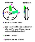
Sure the blades can protrude, and it's a good thing to help hold them rigidly in place. Just cut narrow slots for the blades when you drill and tap the bolt holes. See the pic of mine and the drawing below. The slots would be just in front of each exhaust hole. Sure make them wider, but wider for only the 1st half of the length. No you don't want a cover on the perimeter, because the real action occurs at the blade edge, and you want the exhaust to flow directly in behind the blade and away from the motor.
Peters.JPG
 
Dan,
Be careful not to get too tangled up in complex high speed fans and impellers. Due to the dynamics of the of the spinning motor moving through outside environment, and the fact that we're talking about mid to low hundreds or rpms, I'd suggest keeping it simple. Then different size blades are easy to try. Plus things can be done on the intake side that could greatly influence flow if more is needed. eg Just a simple air dam or duct to slow the velocity outside of the intake holes and increase pressure in that area would surely increase flow significantly. I've kept those kinds of easy mods in my back pocket in case I need more cooling, but that hasn't happened.
 
for sure...for me 70% of the flow is turbulent...I 've seen once a flow simulation on Bike front disc brake, that show that in with the fork etc...there's a main flow but it's mainly a big messing turbulent aera and as most of the Tunning gys think the fin beetween vented disc is to catch the air in fact you understand that as there is no permanent flow it's mostly getting more aera and a cool design...and it's about getting the hot out of it not the air inside of it...
I'd like to see some of your idea to accelerate the vaccum on the entry side...

Dyson stuff was a kind of brainstorming delirium ...imagine a planetary gear inside hub for a trubine to throw air =) :D :D :D
 
John in CR said:
knighty said:
you can fit them pointing in opposite directions on each side, so one side sucks and the other side blows

and/or, google a vented brake disk... you could use somehting like that for the 'out' side if you have enough room... so you could push air in at the outside edge with the blades, and then suck it out from the center of the opposite side ?

Impossible. No fan on the planet works like that, because air won't fight against centrifugal force.

Sean9002 said:
Yup, youd need an unbalanced force applied to the air to make it move in a linear form. matching of forces will cause circulation not venting.

I meant blow in on one side of the motor and suck out on the other

blades on one side to blow air in

centrifugal fan on the other side of the motor to suck the air out... designed like a vented break disk makes it thin, and it'll suck from near the middle, so the air comes in at the outside edge of the motor, across the windings and in towards to the center of the motor and out


EDIT: actually I think we must have our wires even more crossed here... when I saw your replies I assumed you guys thought I meant on each side of the side plate not each side of the motor.... but you could easily have blades on each side of the side plate too as long as they're going in opposite directions... I don't understand where the confusion is around what I posted to make you guys think it won't work
 
a *VERY* rough ms paint diagram

o7pi.png


image on left is twin blade on a single motor side


on the right is the centrifugal center suck fan, front view and edge view
(obviously would have to stagger the vent holes in real life)
 
no

there's an optimum number of blades for the circumference of the van and it's rotational speed

on an ebike, with changing speed all the time, and different wind directions, and different internal and external temperatures, it'll never be perfect

I'd go for an even number of exits, because it'll be much easier to build and also keep the motor balanced

I'd make 12 exits minimum


but this is only he uses the centrifugal design... which is only really worth it if there's not enough space for blades


it might even be worth buying some cheap plastic fans on ebay, cutting the blades off and then modding them to fit and epoxying them on for the outside blades

you'll get a perfect ready made fan blade/shape, it'll be quick and easy to fit, plus you can buy extras to experiment with the best position etc... :)
 
Hey,

what you guys think about adding rad like this one, curved on the outside hub behind the magnets ? dissipating the heat of the magnets would help cooling or is the heat mainley on the windings?
100x30x22 or 132x22x30
132mm%20X%2030mm%20X%2022mm%20Heatsink%20Heat%20Diffuse%20Aluminium%20Cooling%20FIN%20%20eBay%20-%20Mozilla_2013-08-06_10-29-00.jpg
Aluminium%20100mm%20X%2032mm%20X%2018mm%20Heatsink%20Dissipate%20Cooler%20FIN%20%20eBay%20-%20Mozilla%20Fir_2013-08-06_10-29-06.jpg


and do you think that doing some small slots in the hub would work as venting out near the magnets/windings ?
DSC_0053.jpg%20-%20Visionneuse%20de%20photos%20Windows_2013-08-06_10-37-40.jpg
 
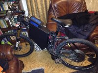
Hi , i made sth similiar, inspiring on Your built, the battery package, I used aluminium and no welding, photos under Yours.

Peter Sternersson said:

file.php


it is actually set to 80A, 18S package:) max is 100V, 100A, but we have winter...:)
 

Attachments

  • unnamed.jpg
    unnamed.jpg
    171.3 KB · Views: 686
what are you settings on the kbl? i have a 96251 and i'm trying to get the most out of it. I can't seem to see more than 118a on my CA. I have it currently set as 70% motor and 100% battery.
 
Back
Top