Swedish Kona DH Cromotor 10kW Kelly *Water cooling?*

Every comment is of value in a forum like this :!:

My bike is actually working good with the throttle connected directly to the Kelly. But it makes the legal mode with 250W and 25km/h while pedaling impossible to work out...
 
Hi,

I've had similar problems with my 18 Fet Crystalyte controller; new FETs still don't work.
I'm interested in your experience with the Kelly, so keep up the posts.
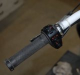
I've used a 3 Speed Switch from ebay which looks pretty good on the bike. It's for a Motorcycle but I've used the High-Low Beam as a Kill Switch wired to the Brake Cut Off, the indicator as the 3 sp switch (L position = Low, Mid position = Medium, R pos. = Wheelie Time). The Horn can be used for the Regen.

http://www.ebay.com/itm/Switch-light-turn-signal-horn-left-control-for-KTM-exc-dual-sport-motorcycle-mx-/390614790248?pt=Motorcycles_Parts_Accessories&hash=item5af274b068&vxp=mtr#ht_2487wt_1400

There are other styles if you search.

Switch.JPG
 
I´m really bad at updatering this thread, I´m sorry... :(

The last couple of weeks I´ve been riding the bike to and from work, totally 20km to and from... Works like a charm!
I have turned the power down to about 160A peak, and maybe 6-7kW continiuous.

Me and a friend with a similar build have been out riding a couple of hours, but we both share the same problem, heat in the motor.

One time we tried to drift on a gravel footballfield, slow going and lots of amps. Straight after we climbed the biggest hill we could find, even slower and even more amps probably.
When we got to the top I read 125 degrees Celsius on my CA.

I have a 10K thermistor tucked in the windings, and it seems to give correct readings.

I have the second version of the Cromotor, while my friend has the first, and I have milled bigger holes in my covers than him. His motor was so warm you couldn´t touch the covers, while mine was warm to the touch, but not so that you burned yourself.

That ridning, even at the 4kW I had set at the time, I totally get that it builds heat, but we went out riding the other day on almost flat terrain, with the same heat problems.

I had a first whack at editing in Sony Vegas yesterday, this is what I came up with after three hours :oops:

http://www.youtube.com/watch?v=hF7DCyMRZMU

And as you can see, motor temp of 100 celsius at one point...
 
So I´m starting to get pissed at my heat problem, (it´s not been an actual problem so far, in ways of anything breaking or loss of power, other than that the bike computer thinks that I have a very high temperature in the motor).

I compare my build with my friend's, who have broadly similar components.

Me , Cromotor ver2, he Cromotor ver1.

Me
, 20S Lipo, he 24S Lipo.

Me, 26 "wheels with hookworm, he 24" with downhill tire. He has 7% less rolling circumference than me, which of course leads to about as much higher RPMs (give or take, I´m to tired to do the exact math right now).

Me about 150A max right now, he 250A, both run Kelly controllers.

Yesterday when we were out on some relatively slow forest riding, my motor quickly up the 90-100 degrees C, while his stayed at 60-70 degrees C.

In a section of harder driving my temp peaked on 135 degrees, his was probably never above 90 degrees. Note that he is running about double the amps compared to me.
We have the same 10K thermistor, placed in the same place (at the outer edge of the windings) and the same version CA.

So to summarize, even though I "should" have a more efficient engine with better cooling characteristics than him, and only runs on half the power will my engine nearly 50% warmer than his...

Today on my way to work, I kept the speed to 60km/h for a long distance (3-4km) on flat ground for testing, the temperature around 50 degrees, 2.5 kW power consumption approx. 15-17 degrees outside.

To test further, I drove a distance (maybe 2km) with two starts and stops at full acceleration, (ie 10-11kW peak) and held a Vmax at 70-75km/h (3.5-4kW power consumption). Then the temperature got fairly rapidly up to 100 degrees. Cools down to degrees again quite quickly if you pull down the speed a bit.

So what the F is wrong here??

The Cromotor V2 is suppose to handle 6kW continiuosly, no way I say, at least not with my configuration...

Will a 24" wheel make a huge difference? I could sacrifice 5-7km/h top speed for lower motor temps...
 
I don^t know the real answer for your situation, but I understand your frustration.

I did a quick comparison in the simulator from ebike.ca. i compared two Clyte TC100 with each other, each at 84V, 100A, and put them next to each other as system A and B with only one difference, system A on a 26" wheel, and B on a 24 inch. Then slide the vertical dotted bar from left to right, and look at the numbers. In the low speeds (at high amps), they are relatively comparable, but above 60kmh, the time to overheat really starts to make a difference. There is a moment where the 26" overheats 3x as fast as the 24".

I am pretty sure that if you push your 26" cromotor to the maximum limits, yours will overheat much faster than "his" cromotor iin the 24".

Other things to look at are different battery to phase current. I have read that Kelly controllers are rated by phase current. However, you should look into how much current you are pulling on the battery side as well. This is the number the CA tells you. Was your peak current much higher than his?

And of course you did not mention whether he had his CA configured to keep temps low by reducing current. Because if he did, it is a perfectly nice explanation... :mrgreen:
 
Lebowski said:
is the controller sensorless ? If not, probably your hall positioning / timing is not good.

The controller reads the halls. This is the one I have.
http://kellycontroller.com/keb7210124v-72v450a10kw-bike-brushless-controller-regen-p-1183.html

I have thought about the timing as well, but I don´t think I can change it in the Kelly. I haven´t looked yet, but I think you can only change between 60 and 120 degrees. Can I somehow measure if the timing is off?

Is the timing a controller or motor issue? The positions of the halls in the motor can´t be changed, they are milled down in the laminations or something like that.

An other thing that might be interesting is that the controller does not get warm at all. I cant even feel it to be above ambiance when the motor is well over 100 degrees.

hjns said:
I don^t know the real answer for your situation, but I understand your frustration.


I did a quick comparison in the simulator from ebike.ca. i compared two Clyte TC100 with each other, each at 84V, 100A, and put them next to each other as system A and B with only one difference, system A on a 26" wheel, and B on a 24 inch. Then slide the vertical dotted bar from left to right, and look at the numbers. In the low speeds (at high amps), they are relatively comparable, but above 60kmh, the time to overheat really starts to make a difference. There is a moment where the 26" overheats 3x as fast as the 24".

I am pretty sure that if you push your 26" cromotor to the maximum limits, yours will overheat much faster than "his" cromotor iin the 24".

Other things to look at are different battery to phase current. I have read that Kelly controllers are rated by phase current. However, you should look into how much current you are pulling on the battery side as well. This is the number the CA tells you. Was your peak current much higher than his?

And of course you did not mention whether he had his CA configured to keep temps low by reducing current. Because if he did, it is a perfectly nice explanation... :mrgreen:

The current that I wrote before is battery current as displayed by the CA. I had short bursts of 150A, and my friend 250A.

I´m actually thinking about just ordering a 24" rim to try out and see what happens. But I can´t really wrap my head around that a increase of just 7% RPM would make 30 degrees difference.

None of our CAs are connected to the throttle, so no current reducing or anything like that.
 
I do have a borrowed old analogue scope, but only with two inputs, and also I don´t have a clue how to hook things up :(

I used it to see if the halls responded as they should, got some square waves after each other so I was satisfied.

I´m almost tempted to order a new motor just to see if there is any difference, would be good to have as a template for my water cooling project. Which is probably totally unnecessary if I got the timing dialed in right...
 
OK, thanks for the additional info.

Any increases in current, and therefore increases in temperature, are mostly seen when the motor needs to deliver a lot of torque. So, with a 24", it is significantly easier for the motor to provide the requested torque as compared to the 24". It is not about the rpm, it's about the acceleration, especially from 0 to 50kmh. So, even with your friend doing 250A from 0 to 5kmh, it may still mean that he pulls only 80A from 5 to 50kmh. If you pull 150A from 0 to 50kmh, you can understand that your motor will overheat quicker.

Going 24" is exactly what I am currently planning for my Big Hit cromotor build. With or without your water cooler... :mrgreen:
 
Just ordered a 24" downhill rim, Hookworm 24" tire and 1,5mm DH tube.

By next weekend I will know how that turns out...

I will try and make some sort of testing cycle, so I really can see what difference it makes.
 
Peter,

Your buddy has a 7% gearing advantage, but what about the total load, you and bike, compared to his? I'm guessing he has a bit lower total load too. His 7% higher rpm also makes his motor cool slightly better.

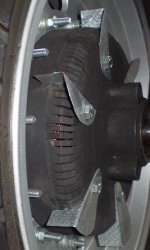
Regarding your air cooling, don't give up yet, because holes in a flat plate doesn't make a very good fan. Some kind of blades are needed, and since you slog it off road, I'd go active to ensure a flow of fresh air even when you're going slow. A handful of small blowers (not axial fans) would work wonders. I run only on the road, so the higher rpm makes blades work great. My latest version flows a tremendous amount of air both through the motor and outside too with each of 6 blades on the exhaust side mounted from the outside through slots cut in the cover. They protrude on the inside to create more turbulence at the copper, and on the outside they are large centrifugal blower blades, which fling air away from the perimeter of the motor. That creates a low pressure area behind the blade causing air to be sucked out of the exhaust vents.

You could easily do some blades similar to mine, and even if they aren't very effective at low speed, they would shield your right side slots from mud or rocks being able to enter.

Right now you're dancing right at the edge. 125°C at the copper isn't terribly hot as long as it's not long duration, and when you see temps rapidly drop when you ease up, that means the stator isn't fully heat saturated, and the heat sinks away relatively quickly to the stator steel. That means just a small improvement in cooling can make a significant difference.

John
 
Would you plz post pics John...
I'm thinking about something like that :
High%20Performance%20E-Bike%20-%20YouTube%20-%20Mozilla%20Firefox_2013-07-18_19-27-10.jpg


in an HS4065 there is no place near the windings or magnets...
 
dan974 said:
Would you plz post pics John...
I'm thinking about something like that :
in an HS4065 there is no place near the windings or magnets...

I started without the blades though I did cut 6 long slots and tapped a threaded hole next to each. The narrow slots alone did flow air better than my other bladeless attempts, since the edge of each slot is essentially a centrifugal fan blade. It wasn't enough flow, and I won't do that again. The blades create tremendous flow. I hesitate to post a pic, because so many simply directly copy what they see, and I already have significant improvements for next time. The improvements from what is pictured below will be:
1. A single large exhaust hole/slot for each blade. One between each bolt hole in the cover like Peter did, but I would make them about half as long and at least twice as wide so it would be protected from debris behind each blade. Since it's few holes I'd take the time to round all sharp edges for freer flow.
2. Instead of cutting the blade slots straight radial, I would angle them rearward to form a more shielded pocket of low pressure behind the blade for air to be drawn out of the exhaust. In my current setup I get a lot of flow from the left to the right on the outside of the shell. Once I get more temp data points, I'll bend the blades rearward to see how much it improves, though I don't expect too much, since my narrow slots are so restrictive and only 2 or 3 are effective immediately behind the blade.
3. With larger diameter motors I would use longer blades and 2 tapped bolt hole for more blade area inside the motor for more turbulence, and still extend the end about 1" past the shell for a nice size exterior portion of the blade.

Here's what mine looks like now on the exhaust side. Don't copy, understand and improve upon the concept.
Hubmonster slots and blades.JPG

This is what I have in mind for the exhaust side slots and holes for next time.


A friend with a fully stocked repair shop has a dense smoke machine, and the motor clearly sucks air into the intake side even at fairly low rpm, 30kph or so, and at the higher rpms I ride it move an incredible amount of air. There's so much flow that even the dense smoke machine didn't give good results for a video, because the smoke dissipated in the air flow with the tube more than a couple of cm from the intake side. Even a foot away from the wheel you can clearly feel that more wind is coming from the exhaust side than the intake.

My other ventilation attempts have all worked pretty well, but the amount of flow with any of those is a joke in comparison to this latest approach due to the large blades at a greater radius.

John
 
Hi John,

and thanks for your great input regarding my problem.

My friends bike weighs probably 10kg less than mine, but on the other hand, he himself weighs 5kg more than me so in the end it´s about the same.

I came up with an easy way of making some scoops to shuffle air into my intake holes. As you say, holes on a flat surface probably makes very little difference.

bild2_zpsb8026a76.jpg


My plan is to cut an aluminum pipe at an angle, and bend out some flanges for screw holes.

If I put them with the intake holes right in the back, it should work like a water wheel or an excavator bucket and forcing air in to the motor.

Some epoxi to fill the gap and the air should have no other place to go than in to the motor...

Might not be the best way, but it´s simple and does not require much modification to the motor cover.

I have about 30mm between the motor cover and my brake rotor, so the scoops can be of a pretty decent size...
 
Hi Peter,

We all go through the "scoop" idea stage, and for me to let it go took someone running the calculations to show how little air it will move. Think about it. All it would end up is a set of tiny axial fan blade. Imagine the small amount of air that would blow with those small blades mounted at that radius at our relatively low rpm. That's not even considering the increased likelihood of them scooping up mud and small rocks. On a positive note they would help flow into the motor if you're able to create low pressure inside, since without them the dynamics of air flow outside makes more intake flow resistance the faster you ride.

Centrifugal fans work in a totally different manner, and other than ducted fans which require inordinate amounts of power, when you want to move substantial amounts of air especially when you need more pressure due to flow restrictions, radial fans are what's used. It's all about velocity at the blade tips.

The beauty of it is that our hubbies are set up beautifully for a simple conversion to make them a centrifugal fan, and my latest approach combines interior blades that has worked pretty well for me in the past along with large exterior blades at the greatest perimeter that a strong low pressure region right at the exhaust vents to greatly increase flow. Plus, since they're mounted from the outside it's simple to fit the interior blades perfectly for maximum turbulence and flow velocity at the stator, and you can adjust the exterior portion of the blades to experiment to find best results.

While spinning up stationary, the blades on mine are easily moving hundreds of cfm of air. Probably more than half is flowing from the left to the right over the outside of the shell, but that's not all bad, since it helps cool the magnets better from the outside. I'm sure the flow is reduced while in motion, but there are a number of things I can do that I know will increase flow. I haven't needed to do them, because the motor doesn't get hot. Mid 80's is the most I've seen at the stator iron, and that's running 245A battery current limit and 30s lipo, so even with my high efficiency motor there's a lot of heat to dissipate, especially from launches.

John
 
very interesting knowledge !, I agree John point of view you can bring a lot more air with depressure than by scoop /area facing thé flow dépressive sucking is able to make a plane fly so imagine how it try to suck the air inside I think the more angle you have of your scoops (Reside) the more the flow is permanent and not tubular around the edge so the watched flow by the air behind the scoops (so inside motor) is faster more efficient and so there taken in movement by the outside flow trying to reach the same speed...maybe the more depressed area opened to the inside you create the more the flow is, maybe if the incoming section is a little smaller than the outside it even accelerate the income, then turbulate inside and is being blow outside...
 
Thank you sincerely both Dan and John, for not just ruling me out as an idiot :)

The scoop idea sounded good in my head, but you are totally right, it probably doesn´t move huge amounts of air.

I played with some cardboard yesterday on the motor, trying to make some sort of blades that would create a low pressure zone around the holes.

Something like this might be able to fit if I rework my chain tensioner a bit, it´s a bit tight here and there. When done in aluminum, I will try to make a rounder edge for less drag and turbulence over the blade.

IMG_0033_zps481a4203.jpg


Another idea if I can´t fit anything on the chain side, could be to buy something like this and fit on the other side.

large.jpg


If you were to remove the motor that sits in the middle, and fit it to the hub instead, then make a disc to block of the outside so to speak, then the air moved by the low pressure created inside the blade assembly must come from within the hub motor itself.


I got my new 24" Hookworm yesterday, along with a 1,5mm thick maxxis downhill tube.
The rim will arrive this afternoon I think, and a friend of mine has some extra spokes in the correct length.
I think it´s time to weld up a jig for lacing and balancing wheels...
 
Your white construction is on the right track except that your blade angle ends at 0° at it's edge. Think of the blade you want to fling air off of the edge using centrifugal force. Yours is at 0° vs mine at 90°, and 90° works great while 0° will do little. At the kind of rpms we are turning you wouldn't want a shallow angle like in your bottom picture which is a nice looking assembly, but obviously is for quite high rpm. My guess would be staying in the 60-90° would be good.

You're on the right track with the white part parallel to the cover, which is needed to block air from simply rushing in from the side to fill in the low pressure region created behind the blade.
 
Slowly but surly I´m starting to get the point, I think :roll:

I have very limited space, both the chain and the chain guide will interfere if I build to much out from the side cover.

But maybe I can make something similar to this crossection.

IMG_00341_zps2559a280.jpg


I feel like I don´t really need the best solution here, if I can get some air flowing through the motor when I´m going fast, and keeping everything maybe 10 degrees cooler, the stator and copper will be able to absorb that extra heat generated when climbing a hill or accelerating hard once in a while.


The only aerodynamic experience I have of this sort is with my race car. The wing is in no way optimal for downforce, but I wanted to keep at least some original look to it (wing is M3 Evo copy) however, with the blade tilted all the way up I feel better traction in the rear, but at the same time, top speed is some what reduced, so drag is added.

Vinge1_zps3c409e66.jpg


Vinge2_zps54d68a25.jpg
 
I don't think getting fancy with airfoil shapes helps us here. It would if we had a squirrel cage fan with openings in front and in back of each blade. We don't, so we want to fling the air away from the perimeter quite strongly such that more air than even hits the blade is force away leaving behind the low pressure region for air from inside the motor to rush in to fill. Do some quick research on centrifugal fans and look at examples.

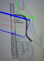
I would change yours to something simple, that I'm pretty sure will work better and be much easier. If you want to do it the hard way, then at least terminate the tail (your trailing edge of the blade) near 90°. In your specific drawing I worry that the air hits the root of the blade and gets deflected up so the turned up tail has diminished effect. The blade I drew in blue, which is simply a piece of thin metal bent at 90°, I know will work. To the extend it protrudes inside the cover passing close to the end windings, it will cool even better.

John

Peters modded for simplicity.JPG
 
you can fit them pointing in opposite directions on each side, so one side sucks and the other side blows


and/or, google a vented brake disk... you could use somehting like that for the 'out' side if you have enough room... so you could push air in at the outside edge with the blades, and then suck it out from the center of the opposite side ?
 
knighty said:
you can fit them pointing in opposite directions on each side, so one side sucks and the other side blows

and/or, google a vented brake disk... you could use somehting like that for the 'out' side if you have enough room... so you could push air in at the outside edge with the blades, and then suck it out from the center of the opposite side ?

Impossible. No fan on the planet works like that, because air won't fight against centrifugal force.
 
Back
Top