torque arm picture thread

I have 2 good thicker torque arms now! and they are VERY well secured!! Because this happened to my first arm in my first 200m with my mac: :oops:
DSC00667.JPG


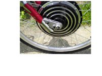
I grinded the axle to an exact fit on one side now:
DSC00693.JPG


I also tried to dissipate the forces evenly on the fork as to stress it as less as possible.
On one side I made use of the eh 'thing/brackets' that normally hold the diskbrake caliper.
I also looked at the direction they want to turn in when you hit the throttle.
DSC00756.JPG

DSC00757.JPG

DSC00759.JPG

DSC00760.JPG

DSC00761.JPG

DSC00762.JPG

DSC00763.JPG

O in fact there are 3 torque arms on it.
:D
 
I got some ideas from this thread for my torque arms so i thought i'd contribute what i learnt.

10mm thick mild steel made using a grinder, drill, file and M6 tap:

001.JPGView attachment 2017.JPG020.JPG


Paul :D
 
torqueplate1.jpg


torqueplate2.jpg


torqueplate3.jpg


torqueplate4.jpg


These plates tolerated 6kW-8kW of very torquey power for a good amount of time, and pretty strong regen as well ( 700-1250w ).

In the end when i dismantled the magic pie bike and sold it's componentry, after almost 2 years of abuse, i still had to bang on the axle to get the motor out of it's dropouts. I looked at the torque plates and they were still perfect. I couldn't believe it.

I've been preaching this method of making torque plates for mid-high power setups for a long time now. They might not have stood up to a Crystalyte 54xx or cromotor hubzilla, but they were pretty effing strong.

Always overbuild your torque mounting bits. You'll pat yourself on the back later rather than kicking yourself in the ass as you gradually pump more & more power into your motor :)
 
here is the axle/dropout setup from the dual pie. Better than clamping dropouts. good for 3.5kw of regen, and 22kw of output power.

2012-02-25170925-2.jpg


2012-02-25170915-2.jpg
 
My solution after mistake of not using them.

Sorry I do not know how to post pictures direct into post.

Milton
 

Attachments

  • E-Bike 002.jpg
    E-Bike 002.jpg
    144.9 KB · Views: 2,598
Paul,
I'm sorry I missed this one back when you posted it. That's pure artistry with a grinder and a file resulting in a perfect torque arm in both looks and function.
John

Timma2500 said:
I got some ideas from this thread for my torque arms so i thought i'd contribute what i learnt.

10mm thick mild steel made using a grinder, drill, file and M6 tap:
View attachment 1

Paul :D
 
John in CR said:
Paul,
I'm sorry I missed this one back when you posted it. That's pure artistry with a grinder and a file resulting in a perfect torque arm in both looks and function.
John

Timma2500 said:
I got some ideas from this thread for my torque arms so i thought i'd contribute what i learnt.

10mm thick mild steel made using a grinder, drill, file and M6 tap:
View attachment 1

Paul :D

Indeed! I hand filed and grinded the arms for my Kona Supreme, mine look terrible, and it was an assload of work. Yours look CNC'd...to have been done by hand is mind blowing.
 
GxPJVl.jpg

Sorry for the crappy picture.

Torque arms were from DOC. Decided they had too much play to be useful.
Chopped them up and tapped them out to make them clamping.
Then Glued to the frame.
Then decided they should be drilled in.
Hard metal. Got really hot drilling it. My bad. This made the glue pop one off.

Oh well. They work fine for 6kw.
Will they work for 10kw?
Loving how easy it is to remove the motor though!
 
Oh man. That looks like one of the bikes that is more difficult to make one for. No meat anywhere.
 
neptronix said:
Oh man. That looks like one of the bikes that is more difficult to make one for. No meat anywhere.

Tell me about it, you shouldve seen me putting the motor on it. Took nearly 4 hours to get it on the frame and the weird thing is I didnt really have any problems keeping the wheel on the frame until I changed the inner tube a few days ago and now the motor works but it doesnt. It happened late this morning after the wheel came out of the dropouts again this time however the motor wouldnt stay running like it usually did the previous times it came off.
 
Hi, i love adjustable torque arm but when i designed my own TA i didn t realized how to make them adjustable. Now i see your nice works and i m a little ambarrassed ..... that s my hard work


img00003201302042336.jpg

img00004201302042336.jpg

img00009201302060945.jpg

img00010201302060945.jpg

img00011201302060947.jpg

img00012201302060950.jpg

img00013201302060954.jpg

img00014201302060954.jpg

img00015201302060956.jpg

img00016201302060957.jpg

img00017201302061134.jpg

img00018201302061134.jpg


MAin cut has been done using waterjet cut. The two small holes are made by press drill by myself. I applied on a decathlon hoptown folding bike and they seems to work properly.
 
Here is the Rev5 of the Ultimate Torque Arms that set i've been succesfully selling since 5 years now.

Over 300 set sold :wink: and still ZERO T-A failure!

Made of the toughest steel and 3/8" thick to have the better compromize between axel lengh and strengh.
(Domex steel is stronger and harder than regular steel or stainless steel) ( Must be lasercutted !)

Original Thread: http://endless-sphere.com/forums/viewtopic.php?f=31&t=29129&hilit=ultimate

file.php


file.php


file.php


file.php


file.php


file.php


file.php


Doc
 
this is on my Ti Mukluk
 

Attachments

  • 20120430_145600.jpg
    20120430_145600.jpg
    194.7 KB · Views: 5,136
  • 20120503_195504.jpg
    20120503_195504.jpg
    206.6 KB · Views: 5,136
Hi , i changed motor and i m going to build new torque arm. I managed to choose adjustable tecnique to better fit the axle in order to implement regen braking. I designed what i think is the best option for my frame.

TA left2.png

This is the left one, the right one will be without brake holder and thinnet at the bottom because of the derailleur. Can someone help me with this design? i think this is the best i can do. The TA is made by one single piece of inox steel (the only one available in italy for this kind o work) and i will drill an hole (the red line) where a screw (m5) will be placed in order to close the torque arm on the axle. Any other hole in the frame will be used to hold in place the torque arm
 
You would have to consider assembly order carefully with the above design. Otherwise turning the screw could move the axle away from the frame, loading your your design with the bikes weight, not just some turning force. This weight would be upon the smaller triangular bit, held only by the stressed hinge like bit and the 5mm screw, that may already be under considerable stress from trying to move sideways.


This is a very good thread. I'm going to adopt the pinch bolt idea, and cut my designs dropout slot just a millimeter deeper than needs be. I want to be sure my bike frame sits on the axle. I'm not trying to take any weight at all. I only have two fixing holes present for my little plate, and they look about M4. They will be troubled by the motor torque alone. I want the bike to take the weight, while my gizmo just stops it turning. Perhaps the goal of everybody, But I need to pay special attention


I don't have a picture, But soon as I do I will post it

Edit: I wonder if anyone has filed out an eaten dropout to take a steel insert. Think 'square roofing nut' And it staying there because it simply can't fall out when it's all assembled.
 
you are right, i will drill mounting holes after setting the pinch screw. I did this when i installed first set of torque arm ( not adjustable ) and it worked quite well. i have 3 mounting holes , i think it will be a very rigid installation but i will pay attention to the distance betweel axle and frame.
 
Back
Top