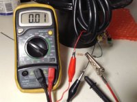
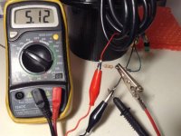
Troubleshooting... am I on the right track?

Synon

10 W
Joined
May 10, 2013
Messages
69
Location
Flagstaff, AZ
So I received a 1kw 48v kit (I believe it's of the yescom variety) from my favorite cousin the other day. He mentioned it needed some work and I see why, the wiring that enters the hub motor was chewed up but fixable, everything was exposed. I pulled the cover off and pulled some clean wire down into the motor and re-soldered everything back together.

Long story short, I hooked up the controller, throttle, and 52v worth of SLA's to test this puppy out and I get no movement. The battery indicator on the thumb throttle lights up with a full battery light, the red button is out so the controller should be on, the wheel spins by hand with minimal effort and is not binding on anything. I took some voltages from the controller/throttle connections and red/black gives me .48v and green/black 0v. Am I correct in thinking my problem is the controller? Is there anything else I can test and are these controllers "fixable" or is it not worth the effort? Or could it possibly be the throttle? I'm trying to find out if there was some shorting when those wires got exposed, I'd guess yes. Would that affect the hub motor at all or just the controller?

This is my first ebike build so I'm definitely needing some help from here, what do you all think?
 
You might wanna check out similar troubleshooting threads ot get an idea of exactly what to test and how, but basically when all those wires get chewed and presumably shorted together, bad stuff happens to the things that are connected to either end of them.

It could be just the controller, or just the halls in the motor, or both. Or neither, and some other problem, but those are my first two suspects.
 
from the controller/throttle connections and red/black gives me .48v

Is that decimal point is correct? 4.8V would be a good sign and to then see it move between 1-4V across green/black when operating the throttle would be even better.

Do you have 3 thick and 5 thin wires running outta the motor axle? If so, what do you see across the red/black thin wires with system powered up? If about 5V then move on to check for hall switching as the motor is rotated.

If your suspect controller doesn't supply 5V to the motor Halls you may need to construct a simple pull-up circuit in order to test/qualify the sensors.

As AW said, there are many useful troubleshooting discussions. Try to read-up, post some pics and describe your test procedures.

Worst case you can probably just replace the controller although qualifying the motor Hall sensors would be an important step before deciding on a replacement controller IMO.
 
A blown controller is quite likely if the wires got chewed while the motor was powered up. Look up testing the controller fets. But if you have it connected to the controller, and it spins easy, blown fets is not likely the problem.

30 bucks gets you a nice motor controller and throttle tester on ebay. Best money I ever spent.

First thing I'd look for, is voltage back to the controller on that on off switch.
 
I've got a never used 12fet controller that came with a 48V yescom kit you can have for $20 bucks shipped if you need it.
 
Thanks all! I've been doing some searching but I don't think I'm using the forum search very effectively (I should do a search on that next :wink: )

I've done a bit more testing so I will try and document everything I've done.

So I disconnected the motor from the controller and did the tests again, the numbers look much better!
Yellow/brown power button wire - 4.3v
Red/Black wires - 4.3v
Green/Black wires - .7v at zero throttle and 2.4v at full throttle

However when I reconnected the motor I get the same numbers as my first test, I didn't adjust any settings on the multimeter.
Yellow/brown power button wire- .48v
Red/Black - .48v
Green/black - 0 at any throttle level

when I had the motor disconnected I tested the motor phase wires and the nut to see if there was a short, everything there looks good.

Hall sensor testing -
Red/black - .11v
Red/blue - .7v
Red/yellow - .7v
Red/green - .7v
When I rotate the motor the voltages don't change at all.

I'll keep searching to see what other diagnostics I can try, or if you all have any suggestions.

wesnewell, hold on to that controller for me! I hope the problem is user error, but if it is the controller I'll definitely take you up on that.
 
Tested hall sensors without the motor connected.
Red/Black - 4.6v
black/everything else - 5v
What the heck?
 
Synon said:
Tested hall sensors without the motor connected.
Red/Black - 4.6v
black/everything else - 5v
What the heck?

Where would it be getting V if the motor is disconnected? Can you post some pictures because what you're describing isn't what I'm used to seeing?

Does your motor have 5 thin Hall sensor wires colored red, black, green, blue, yellow? In addition, there should be 3 thick Phase power wires green, blue, yellow?

Please try to post some pics of the motor wires, controller connectors, etc.
I will try to help you figure this out before spending money on replacement parts.

You may still have wire issues inside the axle/motor and/or damaged Hall sensors. But 1st we need to qualify how all this is actually arranged.
 
Ykick, I am testing the hall leads coming from the controller without the motor being plugged into it. I've included some pictures here:
http://imgur.com/a/olASU

All I did was remove the wire harness, as soon as I plug the wire harness back into the motor the voltages drop.

My motor has the hall and phase wires exactly as you describe, 5 hall of those colors and 3 phase of those colors. I'll post some more pictures to that album as well, thanks for your help! I'll be checking this thread frequently tonight.
 
Okay, you seem to know your way around a meter and how to probe connectors. I suspect the motor wiring and/or Hall Sensors have problem(s). Which likely leads back to the orginal problem of frayed axle/motor wires.

That doesn't rule out a blown controller but the 5V supply more or less coming back when the motor is disconnected is encouraging.

So, what exactly did you repair, solder, etc, with regard to the motor wiring? Can you show a pic or two of that?

Do you think you could rig up a 5V power source and possibly 10k resistor in order to test motor Hall sensors?

If the axle wiring is 100% I'd be attempting to qualify the motor Hall Sensors. You would basically apply 5V to red+/black- going into the motor and then check voltage each individual Hall sensor to black- (ground) while rotating the wheel.

Or, do as Dogman suggested and by a tester.

If motor wires were damaged under power and or power applied after they were shorted it will often blow things inside the controller and may destroy the hall sensors inside the motor.

Not impossible or even that complicated to replace motor hall sensors but it's a job.
 
I just posted a picture of the damaged wires in the album. Unfortunately I did not take a picture of the repair, everything has heat shrink tube on it now and I did test for continuity before wrapping it all up. Basically what I did was pull the cover off the motor and pulled the cable through the axle until the damaged area was inside the motor compartment. I cut all the wires to get rid of the chewed up bits and re-soldered all of them back together, then zip tied it to down and put the cover back on.

I have some old computer power supplies, I'll see if any of them would give me 5v. I don't have any resistors, I'm still quite new to dabbling in electronics, is this a must before testing? And where does it go?
 
if your hall sensors don't toggle and remain at 5V all the time they were shorted to the phase wire when he did the twist off so they have to be replaced, but verify first. no pictures so idea what you are talking about either.
 
Pictures are here: http://imgur.com/a/olASU

The sensors all remain at .85v all the time, and the red/black is at .11v
There are descriptions under each picture as well, let me know if any don't make sense.
 
It just seems as if something's shorted (Hall Sensors and/or wiring?) which is pulling the controller's 5V down.

Old cellphone chargers come in handy for 5V Hall supplies. You may not need a resistor - try it without 1st and see if you have switching if you attempt to power the Halls with an external 5V source.

Be warned, something is likely shorted inside the motor so whatever you use for 5V supply might not be happy camper. Many cellphone wall warts seem to handle dead shorts but YMMV.
 
if there is 5V on the red wire in the hall sensor plug and there is no toggling of the hall sensors when you rotate the wheel and the controller is active then it has blown hall sensors on every phase that does not toggle. phase wires do not matter.
 
I'll see if I can find a charger I wouldn't be sad to lose and give it a shot tomorrow.

dnmun, I'm not getting 5v on the red wire unfortunately, I'm getting .11v when the controller is hooked up to the motor. However when the motor is disconnected the controller gives me 5v, I believe this is why we are trying to find the 5v power source to test if the controller is doing something funky. I should have some results tomorrow, thanks again!
 
Since the hall sensors are in the motor, you can't test them on the controller side with the connector disconnected. To test the hall circuit. connect the halls to the motor. Put your meter negative probe on the black wire. put the pos. probe on the yellow hall wire and rotate the wheel very slowly. You should see the voltage go from ~0V to ~5V as you turn the wheel. If it does, the hall circuit is good. Now do the same for the blue and the green hall wires. If they test good, you know the motor hall sensors are good and so is the hall circuit in the controller.
To test the throttle it needs to be plugged in and power to controller. Check the power for 5V across black and red. Now check the green to black. As you increase throttle, voltage should go up to ~4.xV at wot. If not there's a problem.
I've never seen a hall failure, even on a kit where the guy sheared all the wires off twice at the axle. I've also never seen a hall throttle fail. If these test ok, it's time to look elsewhere.
http://www.youtube.com/watch?v=efYFOHnXh0E
 
Here's a simple test rig to remove possibly faulty controller 5V from the circuit for the time being:
Halltest1a.jpg
Halltest2a.jpg
5V Red+/black- power arrives from a wall wart to motor Hall red/black. 10k resistor connects from 5V red+ to one of the motor Hall switch wires (green in photo) along with the + lead to the meter. Or, you can use an LED instead of the meter which is what the eBike motor/controller tester does.

Rotate the motor and hopefully observe switching between 0-5V. Repeat for the remaining Hall signal wires.

It can be noted that most motor Hall sensors handle up to 30V. 5V isn't really that critical, you can use a 9V battery or pretty much anything between 5-30V. I merely use 5V because that's what the controller supplies to these circuits.

What you're doing is merely qualifying motor Hall wiring and Hall sensors. Since you describe the controller 5V pulling down when connected to the motor I suspect a fault inside the motor.

And/or, it may also be a faulty controller? But doing this test will help determine if you need to go back into the motor for further rework to the wires and possibly Hall Sensors.

If the motor Hall sensors end up being bad you could possibly try a sensorless controller if the motor phase wires aren't shorted? Myself, I would just opt to replace the sensors and wiring inside the motor.

But first thing is isolate where your problem(s) happen to be.
 
Ok, here are the results of the hall test using the method above except for the resister, I did not have one.

9v battery - 8.4v
Red/black wires with battery hooked up - 7.4v
Blue wire - 0.0 to 0.05v - goes back and forth when I turn the wheel
Green wire - 0.2 does not change when rotating wheel
Yellow wire - 0.11 does not change when rotating wheel
 
Synon said:
Ok, here are the results of the hall test using the method above except for the resister, I did not have one.

9v battery - 8.4v
Red/black wires with battery hooked up - 7.4v
Blue wire - 0.0 to 0.05v - goes back and forth when I turn the wheel
Green wire - 0.2 does not change when rotating wheel
Yellow wire - 0.11 does not change when rotating wheel

I see a similar Blue wire result when not using a pull-up resistor. To be 100% certain I would try to find a resistor. Doesn't have to exactly 10k but in that vicinity will help confirm what appears to be 2qty bad Hall sensors (and/or associated wiring).

EDIT - 'had an idea, you could temprarily remove the Green & Yellow contacts from the Hall connector to test if the Blue sensor wire behaves with the 5V supply from the controller? If the 5V doesn't get pulled down then probe the Blue wire while rotating the wheel and look for Hall switching signal.
 
Ok, more testing done with the controller and some of the hall sensors disconnected.

Red black and blue connected - yellow and green disconnected
Black/red - 1.37v
Black/blue - .65v

Red black and green connected - yellow and blue disconnected
Black/red - 3.93v
Black/green - .14v

Red black and yellow connected - blue and green disconnected
Black/red - 3.97v
Black/yellow - 4.78v

None of these changed when I turned the wheel

Red and black connected - blue/green/yellow disconnected
Black/red - 4.00v
 
Is the battery in your meter good? Because this is really odd:

Red black and yellow connected - blue and green disconnected
Black/red - 3.97v
Black/yellow - 4.78v


4.78V is higher than supply voltage measured during any of your testing.

I'd say find a resistor and duplicate the simple test rig in order to be 100% certain. Scavenge from old equipment or grab one from Rat Shack, Fry's, etc.,
 
True, it is higher. It sort of make sense to me only because of my testing on the controller earlier when I disconnected the motor.

Readings from the controller wiring harness with the no motor/sensor wires connected
Black/red - 4.64v
Black/blue - 5v
Black/green - 5v
Black/yellow - 5v

The controller is providing a higher voltage to the yellow/green/blue wires than the red wire. Whether or not that is SUPPOSE to be the case you would know better than I would.
 
Synon said:
True, it is higher. It sort of make sense to me only because of my testing on the controller earlier when I disconnected the motor.

Readings from the controller wiring harness with the no motor/sensor wires connected
Black/red - 4.64v
Black/blue - 5v
Black/green - 5v
Black/yellow - 5v


The controller is providing a higher voltage to the yellow/green/blue wires than the red wire. Whether or not that is SUPPOSE to be the case you would know better than I would.

I see similar voltage measurements with my spare Infineon controller. Slightly higher voltage on the controller Hall signal (blu, grn, yel) wires than the red+ 5V supply.

This could point towards the motor with a possibility the controller may be okay. Only way I know to verify is to test the motor, completely disconnected from controller, with a pull-up resistor as illustrated above.
 
it sounds like the halls are cooked. if it is dropping the 5V on the power when you hook up the power to the hall sensors then it sounds like they are shorted. you can verify by checking the 5V on the throttle wire, red/black and it should hold the 5V when the red/black on the hall sensor power drops since the power to the hall sensors has a current limiting resistor also.
 
Back
Top