Upload Your Circuit Schematics & Requests Here...

In order to prevent Xyster from "spamming" my threads with solicitations for me to look at this circuit I've come here to offer my blessings and to confirm that I've seen it.

Yes, it's possible to toggle between high voltage / low amps verses lower voltage / higher amps and it does work. I've read of dragsters that do this.

Hmmmmm... remember the "battery throttle" concept?

What if you could rearrainge the way you assembled things to incorporate this amperage issue?

Maybe all the subpacks are always in use, but the configuration is changed in order to create a kind of throttle?

With 3.6 Volt increments it's possible... Hmmmmm....

3.6
7.2
14.4
28.8
57.6

So a throttle of five increments? (a logic of doubling voltage)
 
In order to prevent Xyster from "spamming" my threads with solicitations for me to look at this circuit...

Hmmmmm... remember the "battery throttle" concept?

That's why I thought you'd appreciate it and perhaps wish to implement/improve upon it. For some people I guess, the only good ideas are their own.
 
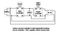
For a discussion of this circuit, see:
http://endless-sphere.com/forums/viewtopic.php?t=370
 

Attachments

  • RegenController.jpg
    RegenController.jpg
    19.7 KB · Views: 9,952
OK, here's a version for brushless motors.
Remember, this has not been actually tested yet.
Who wants to try it?
For a discussion of this circuit, see the same place:
http://endless-sphere.com/forums/viewtopic.php?p=4658#4658
 

Attachments

  • Brushless Regen controller2.jpg
    Brushless Regen controller2.jpg
    22.6 KB · Views: 9,902
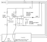
OK, here's an updated version of the current limiter add-on circuit.
This goes inline with the throttle and gives you a knob to adjust the current limit. The upper and lower limit 10 turn trim pots go on the circuit board and are adjusted to set the upper and lower current limits of the control knob. The control knob goes where you can get to it easily, and can be extended by wires any distance from the circuit board.

The action of the control knob should be linear between the upper and lower limits.

The value of the shunt is not critical, since you can adjust the limits over a fairly large range. It is critical to make sure the shunt wires aren't reversed and that the shunt is connected to the battery negative.
 

Attachments

  • Current Limiter 5.jpg
    Current Limiter 5.jpg
    32.7 KB · Views: 9,843
good idea using the multiturn pots, that's what i did in mine. The input to the pwm chip is right around 4.2v and it is just a few millivolts we are controlling, so the 10 turns are perfect.

did you try using the internal shunt, which on my 35A controller is almost exactly a milliohm?

-bob
 
No, I haven't even tried it with any shunt yet.
The internal shunt would be perfect and very easy to tie into. There's plenty of room inside the controller for a small board too. The whole thing could be built-in.

My design was really intended to be an add-on that didn't require any mod to the controller itself and was just inserted in-line with the throttle cable.

The LED also allows you to adjust the zero point and tell the state of the output for troubleshooting purposes.

Also keep in mind this is just a current limit adjuster. You can get the same effect by just sticking some resistors to the board and tweaking the built in limiter circuit.

The current mode throttle circuit is slightly different. I'm still refining that one. An early version of that is on the first page of this thread.
 
Hi guy's
Being electronically illiterate i don't know if this is possible,
I'd like a net battery meter something that you input your AH + voltage (or better still it learns your capacity) making it adaptable to any bike. It constantly monitors your used amps at the constant voltage (subtracts from total)and tells you how much as a percentage (or some indicator) of full power you have left.


Allso a button to take you back in time to just before you did that thing that trashed your bike ! :D
 
29a,

Check out this thread and see if it is similar to what you are thinking of.

http://endless-sphere.com/forums/viewtopic.php?t=367

I'm working on it for myself right now, but may be inclined to sell kits in the future if it works ok.

If you have any suggestions for improvement, feel free to add them to the thread. I've only got about 400 bytes left out of the measly 8K of memory on the microcontroller I'm using, but may be able to add a few more things.

As for the bike detrasher, I'll start work on the flux capacitor at once.
 
Here are schematics of 36V 9Ah made of e-moli V18 packs which are under contruction right now during my vacation.
I will be installing double Milwakee chargers on bicycle , complete with the cord. So you can see each charger is switched between 3 batteries.
Before that batteries are separated.
Opportunity charging here in Alberta is aboundant with power left on after winter in many outside receptacles.

MC
 
miro13car said:
Here are schematics of 36V 9Ah made of e-moli V18 packs which are under contruction right now during my vacation.
I will be installing double Milwakee chargers on bicycle , complete with the cord. So you can see each charger is switched between 3 batteries.
Before that batteries are separated.
Opportunity charging here in Alberta is aboundant with power left on after winter in many outside receptacles.

MC

I'm doing the same thing presently with my 4 Dewalt 36V pack. I have a 2s2p config 4.6Ah 66V and I have 2 cahrger for those. But i'm using unly 1 bms per 2P pack and it work great. I plan to put my 2 charger on the bike too, but i wonder about vibration and the pcb. Maybe i will put some silicone on the components.

I plan to use all 4 seasons including winter, so i need to make it perfectly resistant.

At 33V 4.6Ah (2Pack parallel) I can get 134Wh with fully charged pack with 29V cutoff.

i was impressed to discover that to get 134Wh output, I need to charge using only 140Wh!!!.. The charge is very efficient with the A123!

Doc
 
29a said:
Hi guy's
Being electronically illiterate i don't know if this is possible,
I'd like a net battery meter something that you input your AH + voltage (or better still it learns your capacity) making it adaptable to any bike. It constantly monitors your used amps at the constant voltage (subtracts from total)and tells you how much as a percentage (or some indicator) of full power you have left.


Allso a button to take you back in time to just before you did that thing that trashed your bike ! :D

You need the Cycle Analyst from e-bike.ca. (Formerly called the DrainBrain). I have a "beta" version, but it has worked flawlessly since I installed it.
 
i've got a request...

Can anyone explain how I could rig up an overheat cutout for the motor? Thermister in the moter, could it be configured to use the controllers LVC circuit? Or if too complicated, how about just a warning light that comes on over 80 degrees C?
 
That's a good idea.

If a second diode was added to the LVC part of the circuit, you could use it to fold back the power when the temp gets too high.

Most electronic thermometers have an analog signal at some point (on the thermistor, I guess). You could find out what voltage corresponds to your desired set point, then design a comparator that trips when you exceed the set point.

The details of this would somewhat depend on the thermometer used.
 
Jozzer said:
i've got a request...

Can anyone explain how I could rig up an overheat cutout for the motor? Thermister in the moter, could it be configured to use the controllers LVC circuit? Or if too complicated, how about just a warning light that comes on over 80 degrees C?

Fixed temperature cut-out (or cut-in) device or thermister could be used.
You have to embed it in the motor (winding or core) and lead the wires out to the controller for pulling down like the LVC as suggested by fechter.

Fixed temperature cut-in device could be used to provide an warning light above a fixed temp.
 
Good point. The Vego motor had a fixed temperature thermostatic switch that basically shorted out the throttle signal when the motor got too hot.

I even have some around somewhere. This would be much easier to connect. The downside is there was no warning when it cut out. You could be in traffic and suddenly kick out. I would prefer the warning light.

Another option would be to use the thermostatic switch to cut the current limit in half or to a lower value so you don't completely stop when you hit the overheat temp.

These should be available from electronic parts places like DigiKey.
 
So, I could use one of these? http://rswww.com/cgi-bin/bv/rswww/searchBrowseAction.do?Nr=avl%3auk&N=4294963324&name=SiteStandard&forwardingPage=line&R=2532701&callingPage=/jsp/browse/browse.jsp&BV_SessionID=@@@@1406644693.1188511459@@@@&BV_EngineID=cccdaddlldfgkgicefeceeldgondhgj.0&cacheID=ukie . And connect it to warning LED on a simple switch circuit..
See anything on that site that would do a better job? (smaller the better, Puma's are a bit tight for space!) I'm not sure what i'm looking for (Noob!)
I guess the other easy option would be to wire in above thermostat with the brake cutout (so light couldnt be ignored :roll: ). To do this I would need one that closed when hot, is that right?

As far as the NO WARNING before it cuts out goes, thats ok, theres not much warning before they overheat and die either, at least after the embarrassing moment you can still ride home under power :?

Is 80C a reasonable cut off temp?

Thanks for helping guys, I wouldn't have got half this far without you!
 
Any easy circuits to be made to handle adjustable low voltage cutoff for a pack discharger?
And on a similar note, an adjustable max voltage cutout for charging?

Bonus points for a cicuit that does both :lol:
 
You want to discharge the batteries on the bench?
How much current would it need to handle?
 
Maybe a few amps? Or just a circuit to cutout leaving a relay to handle the current (attached to whatever load I can find...I have a lot of spare peltiers right now for instance)
 
Jozzer said:
Any easy circuits to be made to handle adjustable low voltage cutoff for a pack discharger?
And on a similar note, an adjustable max voltage cutout for charging?

Bonus points for a cicuit that does both :lol:

you start out with a relay in the current carrying line for both configurations of low and high cutoff. then you cut off power to the relay coil when the voltage drops below or rises above the limit.

if you want to get fancy choose a relay with multiple contacts so one set can be used to latch the relay on. if you do not do this the relay can just be on any time the voltage is inside the operating range. with a latching configuration you have a pushbutton start and an automatic cutoff.

i know i have described this idea somewhere else, but my short term memory is not what it once was, and i forget where. if this explanation is not enough i could draw a schematic if you give me the desired setpoint range.

for low voltage cutoff, you could keep the relay coil energized with an npn transistor that was kept turned on by a voltage divider off the battery voltage, set so that when the voltage drops to the preset cutoff point the transistor turns off and the coil opens.

for the high voltage cutoff, you could use a second transistor that steals away the base current that keeps the first one turned on when the second transistor is turned on by its voltage divider. this will work better with the latching configuration, since that will prevent the coil from being re-energized once the trigger point has been achieved.

a combination of zeners or 3 terminal regulators with the resistor network will make the results more reproducible.
 
i have decided to wring out the schematic for the throttle portion of the controllers, as i have not seen it anywhere, and i am thinking of ways it might be improved, and looking at the best way to integrate the cycle analyst into my existing controllers.

i have not seen any schematics except for the current limit portion of the 3525, but if i missed something someone please let me know.

as justin pointed out to me, the ebrake line can be used as the input for the pull-down current/speed limiter. the ebrake input is connected to the throttle line through a diode and 10k series resistance, so the control line from the limiter, or any other device that functions by pulling down the throttle signal, can simply be connected to the ebrake line without the need for any additional circuitry. additionally, the thermal cutout on the pcb is connected to this line. the thermal cutout simply grounds the throttle signal when the board overheats. this way it is not necessary to switch large currents directly.

i will keep going with my analysis; i can see why others have had trouble with this part of the circuitry, there are a lot of vias and multiple interconnect points. at least they use the lm358 and all the parts are well marked. i don't like to continually re-invent the wheel, so any schematics that are floating around would be welcome.
 
bobmcree said:
as justin pointed out to me, the ebrake line can be used as the input for the pull-down current/speed limiter. the ebrake input is connected to the throttle line through a diode and 10k series resistance, so the control line from the limiter, or any other device that functions by pulling down the throttle signal, can simply be connected to the ebrake line without the need for any additional circuitry. additionally, the thermal cutout on the pcb is connected to this line. the thermal cutout simply grounds the throttle signal when the board overheats. this way it is not necessary to switch large currents directly.

Thanks for this piece of info which is helpful.
 
Sounds like a start Bob, but I'll need more than that to get going :lol:

Got time to put a circuit diagram down? A good start would be low cuttoff @ 29v and high at 37v to handle a 10cell A123 pack. Variable would be a nice touch, or an easy way to convert to other voltage ranges.
A difficult way to change voltage range would do at a pinch (ie changing resistors etc).

Come on hero's...show us why we love you so :lol:
 
Back
Top