Upload Your Circuit Schematics & Requests Here...

Jozzer said:
Sounds like a start Bob, but I'll need more than that to get going :lol:

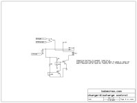
here is a quick sketch of the general idea. there are two resistive dividers, each provides the turn on voltage of the transistor at a setpoint. the cycle is interrupted by q1 turning off, which occurs either when the voltage on its divider drops or the voltage on the q2 divider rises to turn on q2, turning q1 off. when i have a bit more time i will figure out the resistor values or refine the circuit a bit, but this basic idea should work with 1k pots and 10k resistors.

zeners or voltage regulators could provide more precise control by setting the voltages for the dividers
 

Attachments

  • CHARGE_DISCHARGE CONTROL REV B.jpg
    CHARGE_DISCHARGE CONTROL REV B.jpg
    75.1 KB · Views: 2,794
Excellent, I can work with that. When I know which parts to order I'll get right on it:)

*runs off to find out how a resistive divider works*
 
almost any npn transistor will work. 2n2222 would be a good choice for small relays. i used a 12v DPDT relay, which would require a regulated 12v supply or dropping resistor, but if you used 2 SPST 12v relays with the coils in series you could drive them with the charger voltage and it should work fine.

you want the dividers to produce about a volt at the transistor base to turn them on, for each case, so you the value of the pot needs to be 1/29 or 1/37 of the voltage applied. you need a few milliamps to make sure the transistors are turned on enough to drive the relay, so 10k would be fine for the top resistor, then you would need about 300-500 ohms for the pot.

with 10k on the topside and 30v you would have 3 ma to drive the base of the transistors, and if they have a beta of 50 or more that will drive a 150 ma or smaller relay coil.

if you used 500 ohm pots and 10k resistors and put 220 ohms on the bottom side of the pots you would have finer adjustment range, but 1k pots would work.

this circuit should switch within about half a volt of the setpoints worst case, which is good enough for most purposes. a much more accurate result could be obtained with comparators driving the transistors, with one input of each comparator set with a pot and resistive divider from a regulated voltage to the setpoint and the transistors just used as switches. the turn-on voltage of the transistors will not vary much, but if it moves .01v that will be magnified by the resistive divider to 0.3v or more.

the schematic i quickly knocked out is only meant to be a starting point. since there seems to be a need i will refine it for better accuracy and post an improved version later this week.

if somebody wants to beat me to it and draw up a more accurate circuit i will not be offended.
 
Thank you :D
 
there is an issue i should point out in the basic crude design. the setpoint adjustments are dependent on the base-emitter voltage of the transistor used to switch the relay coil, and this changes slightly with temperature.

for best results you should use a relay with a low current coil, or a big power transistor that can handle a larger coil easily without much heating. if you heatsink the transistor it will help a lot, as will making the voltage adjustments after the relay has been on for awhile and the transistor temp is stable. q1 will rise in temp since it drives the coil, but q2 only switches a few milliamps so it will just move with room temp.

these are the reasons that for better accuracy you use comparators to switch the transistors at the right voltage thresholds.
 
I'll bear that in mind. I have a nice relay here, but its coil is towards the higher end of your recomendation. I've ordered one that uses half the power, I hope that will do it.
Bits should be here tomorrow, I look forward to having a go at it. Bench testing and improving it should keep me busy for a few days/weeks :lol:
Will this circuit work with any voltage pack thats within spec (think the transisters were rated 40v)? I realise the cuttoffs would need recalibrating..
 
Jozzer said:
I'll bear that in mind. I have a nice relay here, but its coil is towards the higher end of your recomendation. I've ordered one that uses half the power, I hope that will do it.
Bits should be here tomorrow, I look forward to having a go at it. Bench testing and improving it should keep me busy for a few days/weeks :lol:
Will this circuit work with any voltage pack thats within spec (think the transisters were rated 40v)? I realise the cuttoffs would need recalibrating..

with a simple voltage divider, the voltage set with the pot needs to be the turn-on voltage of the transistor,about 1v. this is vr1 / vr1 + r1 = 1/trigger voltage as long as you keep the voltage in the general range below 50v this should be fine.
 
Trying to assemble the circuit now, i'm a little confused about the earthing. The triangles in the diagram (under vr1 and sw1, and on the relay latch at the top) are to be connected to negative? Of the 12v coil supply? Or the charging packs? or did you intend that the 12v supply would be taken from the charge pack and share a common negative?
If so, should I drop the voltage to 12v with a resistor, or tap 12v from the most negative 4 cells in each pack I charge?

Try to do a favour and get a thousand questions in return :lol: THats what you get for helping a noob! :roll:
 
the +12 is just to drive the relay and can be created with a 3 terminal regulator like the 7812, or a current limiting resistor could be used to drop the voltage. the 7812 will only work with input voltage <35v or so, but i have used them up to 40v. the low current required to drive the relay should make it ok, or you could just put diodes like a in4001 in series with the input of the 7812 to drop the voltage a volt each.

the simplest thing to do is to use a series resistor between the charger and the + end of the relay, making sure the resistor can dissipate the required power. you can calculate the resistor using ohm's law. i'm sorry, but if you cannot do that this may be beyond your present skill level.

the circuit i suggested assumes that you set the pots at the end of charge or discharge, which may have been a bit misleading. i apologize for assuming you should know that, which is an invalid assumption on my part. in order for the voltage divider setpoints to remain stable, they must be divided down from a regulated or known voltage.

the low voltage cutoff will work based on using the cutoff voltage for the value at the top of the resistive divider at the end of discharge, because above that voltage there will be enough to keep q1 on. . the high voltage cutoff will work the same; at voltages below the endpoint there will not be enough voltage to divide down to trigger q2.

if your supply voltage is constant, the current to the battery will decrease as the state of charge increases. most battery chargers use loosely regulated supplies, or they use a constant current, which increase in voltage with the state of charge.

if you adjust the pots during actual use the voltage dividers would be based on the voltage of the charger at that state of charge or discharge,so it should work. as i said, this circuit is just a rough starting point, and a regulated voltage to the top of the voltage dividers would make it much more accurate.

when i have a bit more time i will analyze the function of the circuit more thoroughly and i may have some refinements, but if you adjust the pots to trigger the respective transistors at the end of charge/discharge i think it will work ok. nobody would likely build a commercial product with this simple circuit, but it is a place to start.

when calculating the trigger points, the voltage of the charger at those points must be known. thus, for the end of charge, we assume that say 36v is the proper level. the actual voltage will be divided down and if the pot is adjusted to trigger the end of charge when the voltage is 36v it will work properly. you will have to watch the system with a meter and set the pots to end charge/discharge when the voltage is close to the endpoint.

don't feel like you are less than somebody else because you don't know this; i'm sure you know things i don't. there is some pleasure in the application of my knowledge to help somebody else achieve their desired task, otherwise all that time i spent studying is not worth much in the grand scheme.
 
The circuit is built, apart from the 12v regulator which I have just ordered.
I've reread your last post a few times, and cant see that you answered...the three connections terminating in triangles/arrows in your diagram are grounds? Do they just ground to each other, or are they connected to the pack negative? I apologise if you answered indirectly and I missed the point...

Thanks very for your help, it's a bit late in life to be taking the first steps in electronics, I can't believe to this day that none was taught to me in school, or that to this day I've not applied myself to the task of learning. Call it my midlife crisis, but thats going to change! Seeing how easily you/Fetcher can achieve the results you seek has been very inspiring.
 
Jozzer said:
The circuit is built, apart from the 12v regulator which I have just ordered.
I've reread your last post a few times, and cant see that you answered...the three connections terminating in triangles/arrows in your diagram are grounds? Do they just ground to each other, or are they connected to the pack negative? I apologise if you answered indirectly and I missed the point...

Thanks very for your help, it's a bit late in life to be taking the first steps in electronics, I can't believe to this day that none was taught to me in school, or that to this day I've not applied myself to the task of learning. Call it my midlife crisis, but thats going to change! Seeing how easily you/Fetcher can achieve the results you seek has been very inspiring.
sorry i forgot to make that clear. the triangles are all ground which is the battery negative and the starting point of all the voltages. the general nomenclature is to use that symbol as ground.

it is never too late. i am retired from 35 yrs as an electrical engineer and am going back to school to study high energy physics next year.

here is a good place to start which will help you understand the circuit you are building: http://www.electronics-tutorials.com/basics/ohms-law.htm

there are no dumb questions; only people who are so dumb they think they know everything and don't need to ask.
 
bobmcree said:
there are no dumb questions...

Aren't there?
Why aren't there?
Can you prove that?
Do you think you know everything? If not, isn't it possible you just haven't bumped into a dumb question yet?

Until now, maybe.... :wink:
 
Toorbough ULL-Zeveigh said:
there are only dumb question askers.

As evidenced by what besides their dumb questions?
 
Thanks again Bob, think I'm ready to test once the 7212 gets here :D

There was a secret purpose behind Xysters Dumb questions, you'll notice he now has more than 3000 posts :wink:
 
Toorbough ULL-Zeveigh said:
This kind of evidence:

Aren't there?
Why aren't there?
Can you prove that?

So then, might we conclude that dumb questions are those questions purposely designed to annoy rather than solicit an answer?
There was a secret purpose behind Xysters Dumb questions, you'll notice he now has more than 3000 posts

You're correct that there was a secret purpose -- to answer the question 'what is a dumb question?'. The postings milestone was in no way part of the objective. :)
 
Jozzer said:
Thanks again Bob, think I'm ready to test once the 7212 gets here :D

There was a secret purpose behind Xysters Dumb questions, you'll notice he now has more than 3000 posts :wink:

i hope you mean 7812. since your charger could get up to 40v you really should protect the 7812 from seeing too much voltage, a 12 to 15v zener in series with its input will keep the voltage it sees from getting above 25v and because the current requirement is low a 1 watt zener will be plenty.

i hate to see you keep ordering parts just because i forgot to tell you something. contact me offlist and i will send you a zener, i have lots and they are cheap.
 
OOPS, just realized you are in the UK and it would take awhile to get a part to you.

as i mentioned before the 7812 is rated to 35v and will probably be ok, but to avoid you burning out a part the ideal situation would be to drop the voltage a bit from the max your charger produces.

you can't use a dropping resistor, because the current will be very low when the relay is off, and the resistor would need to be high enough to drop at that low current. if you have some regular diodes they have a forward drop of about a volt, if you put the positive on the anode and look at the voltage on the cathode (bar end) you will see that the voltage drops across the diode. if you put 5 diodes in series this way that would protect the regulator up to 40v.

a single zener pointed away from the battery will do the same thing, any zener voltage from 5v up to 15v would work, and would provide protection up to 35v + the zener voltage.

i know the guys are chuckling that this turned into a bigger project than i originally expected, mostly because i just quickly knocked it out without enough thought. free advice is usually worth what you pay for it :)
 
Yes I did mean 7812. To protect the circuit, i'll start off experimenting with half a pack.
Ultimatly, if this proved reliable enough for an everyday charger cutoff, it would be nice if it could manage a couple more cells, making full charge voltage around 44v, so I may go looking for another way to get the stable 12v. Also there would be the risk that a CC charger would let the voltage it sees go very high if the pack were removed whilst it was turned on.

Hehe, i bet more than half the times you post a helpfull diagram like this the person who asks never actually uses it. Bet you'll think twice before drawing a circuit willy nilly next time I ask :wink:

Thanks for the offer of sending bits, had I known you were offering this circuit in kit form I would have asked straight off :lol: Clearly this job takes patience, I can wait..
 
you might consider using a simple wallcube type power supply or anything that will deliver the 14v-35v that the 7812 can handle. you would just tie the negative of that supply to the common ground, and then power just the relay coil from it.

yep, sometimes in my desire to help someone i assume that they know more than i should, and sometimes i put ideas out there without completely thinking them through. like i said, free advice is usually worth what you pay for it.

the problem with using some of the cells in the pack under test is of course that the cells providing the relay current will drop out first. depending on the fraction of the total load that error could vary in magnitude. for example, if you were discharging the pack at 10A a 2.2 Ah a123 cell would discharge in about 12 minutes, and if the relay draws 100 ma. that would give you a value about 1% below the actual value. if you were only discharging at 1A it would be a 10% error.
 
My charger runs from a 13.8v psu, could I use this directly, without the regulator? I'll need to test it, but I would think its a stable voltage except for perhaps when the charger loads it as it kicks in.
Actually, is there any reason why I cant use another/seperate 12v battery for now?
 
Jozzer said:
My charger runs from a 13.8v psu, could I use this directly, without the regulator? I'll need to test it, but I would think its a stable voltage except for perhaps when the charger loads it as it kicks in.
Actually, is there any reason why I cant use another/seperate 12v battery for now?

yes and yes. the relay will handle 13.8v and would not be damaged by a turn-on spike. just connect the minus to ground and the plus to the top of the relay.

be aware that some relays have a diode across the coil to absorb the spike when the magnetic field of the coil collapses on disconnect. the arrow (cathode) needs to be connected to the positive or the diode will conduct and the relay will not work
 
Toorbough ULL-Zeveigh said:
xyster said:
So then, might we conclude that dumb questions are those questions purposely designed to annoy rather than solicit an answer?
Very perceptive.
I thought you might take that the wrong way.

Who me? I take all your insults the right way. :D
 
Back
Top