Using the Wangdd22 1500W 30A DC Boost Converter on an ebike

Regarding the new one....

Component differences may be causing the lower output, but it may also have design differences.

You could try changing out all the parts that are different between the new and old one, to match the old one's values and/or part numbers, but if the design is different that may not do what you want.
 
amberwolf said:
One thing you *don't* want to do is glue the liners down. If they are fixed to the inner surface of the tire, then they won't move to let stuff slide across their surfaces and deflect the points away from the tube, or let them push inward, and the stuff will instead puncture the liner and your tube.

Turns out I was wrong and one of the other staple got through to the tube. I didn't catch it at first because the Slime plugged those holes.
I used rubber cement to locate the liner. It does not adhere to the plastic liner very well, but well enough so I can be sure that the liner starts out positioned well.
 
As long as it doesn't keep the liner from moving away from the tire's inner surface durign deflection instances, it'll probably be ok.

It's probably good to lightly stick it to the inner tire surface against side-to-side movement, as that should help minimize or prevent the squiggle-effect I tend to see with them over time (especially in the heat). :)


Don't forget to contact Slime about the liner--they'll replace it and the tube since somethign did get thru the liner, and they guarantee that won't happen. ;)
 
amberwolf said:
Regarding the new one....

Component differences may be causing the lower output, but it may also have design differences.

You could try changing out all the parts that are different between the new and old one, to match the old one's values and/or part numbers, but if the design is different that may not do what you want.
I'll probably order some capacitors and see if I can revive the old booster. Going beyond that is probably not worth the trouble.

I gather that you think the minor difference in the pot resistance is not likely to be at the root of the output differences then?

The designs appear identical. At least the PCB seems to be. Though I haven't done a component-by-component detailed comparison.
The specs are the same and with a fresh charge should draw 25 amps. Right now I'm guessing that my first booster was probably running a bit above spec and this one is a bit below. Probably just product variation and/or refinement. I'll double-check the current meter and see if this one is drawing 25 amps. I've been looking at watts, not amps.
 
wturber said:
I gather that you think the minor difference in the pot resistance is not likely to be at the root of the output differences then?
It's possible; sometimes it's just a part tolerances thing. You could unsolder the pot from the old one and replace the one in the new one with it, to test.

But you did say some of the capacitors are also different values. If those are just input or output filter caps, then they only really affect the smoothness of the DC under higher loads. If they are parts of the switching circuits, then they could affect other things depending on where they are and what those sections do--if they affect the pulse widths, they'll affect the total amount of power available.


The designs appear identical. At least the PCB seems to be. Though I haven't done a component-by-component detailed comparison.
If the PCB is the same, then component differences would change the way it works, because they're all wired together the same.

If it is run by an MCU or other "smart" / programmable chip, then the programming could be different, so operation could be different. If it's a dumb chip that always works the same regardless, then the chip won't change antyhing unless the passive stuff connected to it that determines it's operation is different.

(like with a 555 timer chip, the resistor and capacitor values affect the frequency and pulse width of the output when it's used as an oscillator).


I've been looking at watts, not amps.
Watts should be the same if voltage is the same and amps are the same. If voltage is teh same on input and output, and watts are lower, then amps will be lower. If the amsp and watts are the same, and input voltage is the same, then output voltage will be lower.
 
In DC converter designs the buck-boost designs have lower efficiency and increased complexity and cost, they are generally not used much except when really needed, and usually not at high power.

If you want to turn a boost converter off it could be done with a diode from battery to output and SPST switch on the converter input which may be safer. When the converter is boosting the diode will be reverse biased and won't conduct, and when the input power to the converter is removed the current will flow around the booster. The booster circuits generally contain a diode already that will block current flow back into the converter.

The cheap converters are often data-sheet example designs and they rarely have the correct components and adequate safety deratings and may be lacking in components that are generally added to real designs. Apply your own deratings and run well below stated maximums for reliability. Checking the specs on the parts before using the unit may reveal incorrect voltage ratings, we've seen that, I think it was in a discussion here on battery charging with them and the diodes were not up to the required ratings. They don't always use good parts, and may have counterfeit parts in them as well. Also make sure to avoid exceeding every spec, it is easy to miss one and stress the components in some way.

An intermittent output connection when outputting current can cause incredibly high voltage spikes to be generated from stored energy in the inductor, enough to blow components, especially the semiconductors. So the loose connector may have blown the converter.

A quality controller with field weakening is probably be a better way of solving this problem. It is similar to boost conversion, but it occurs in the motor and controllers set up for it are likely to have the proper design as well as not introducing additional loss items to the power path. The LVC will be handled better and it won't add another item that has to be mounted, cooled, and sealed from the weather.
 
Alan B said:
In DC converter designs the buck-boost designs have lower efficiency and increased complexity and cost, they are generally not used much except when really needed, and usually not at high power.

I appreciate the detailed reply. Thanks.

My estimate (comparing watt meter output to watt meter input) is that this booster operates right around 95% efficiency. My (admittedly over-the-top) headlight consumes more power. The booster runs cool. The fan never kicks on and it never seems any warmer to the touch than the ambient temperature. My watt-hour/mile rates seem to be pretty typical. If anything, a bit better than average for a conventional upright bike. So for my commuter uses, a 5% loss is insignificant. I might care more for longer distance touring. But I'd save more by getting a less powerful headlight.

Alan B said:
If you want to turn a boost converter off it could be done with a diode from battery to output and SPST switch on the converter input which may be safer. When the converter is boosting the diode will be reverse biased and won't conduct, and when the input power to the converter is removed the current will flow around the booster. The booster circuits generally contain a diode already that will block current flow back into the converter.

You've lost me on the bit about turning the booster off. I pretty much want it on all the time. The quiescent current is 15ma. These days I leave the battery constantly hooked up to the watt meter, booster and motor controller. The drain is too small for the watt meter to register. Though after 12 hours I can see a very slight voltage drop. The only reason I had it disconnected before the booster died was because I had the bike parked and locked in a public place.

The booster inputs are protected from shorts and reverses. It is unclear what the output protection is. It seems tolerant of whatever the DD motor sends back when coasting. However, it complained and shut itself down when I enabled the e-brake/regen function which presumably sent a lot more current back toward the booster. For all I know, that little experiment damaged it. Though I did that last winter and have put about 2000 miles on the bike since then.

Alan B said:
The cheap converters are often data-sheet example designs and they rarely have the correct components and adequate safety deratings and may be lacking in components that are generally added to real designs. Apply your own deratings and run well below stated maximums for reliability. Checking the specs on the parts before using the unit may reveal incorrect voltage ratings, we've seen that, I think it was in a discussion here on battery charging with them and the diodes were not up to the required ratings. They don't always use good parts, and may have counterfeit parts in them as well. Also make sure to avoid exceeding every spec, it is easy to miss one and stress the components in some way.

I'm not sure about all the parts, but the capacitors are nichicon which appear to be in the top-tier category. I run well within the input and output voltage specs, but I am running at maximum current output have for the 3000 miles I've run it. Of course it isn't pulling that current all the time. I run PAS about 90% of the time now and that limits current to about 17 of the 25 amps allowed per spec. Typical draws are in the 7-12 amp range I think. About 1/3 to 1/2 of the booster's limit. But I do use full throttle every now and then as a "boost" which is puts the booster at the spec limit of 25 amps while in the 31-60 volt input range. When below 31v, the spec is 30 amps. But even when pulling full power going up a hill, the booster's cooling fan never turns on and the heatsink never gets even warm to the touch. So if I was stressing anything, it seems unlikely that it was a heat stress.

Alan B said:
An intermittent output connection when outputting current can cause incredibly high voltage spikes to be generated from stored energy in the inductor, enough to blow components, especially the semiconductors. So the loose connector may have blown the converter.

The disconnection was on the input, not the output side. When I removed the failed booster the output connections were still solid. And the input wasn't loose, it was simply partially engaged and completing the circuit through the pre-charge resistor in the XT90 connector. My guess now is that the booster had already failed and the fact that the current was flowing only through the pre-charge resistor is what kept the booster's fuses from blowing right away.

Alan B said:
A quality controller with field weakening is probably be a better way of solving this problem. It is similar to boost conversion, but it occurs in the motor and controllers set up for it are likely to have the proper design as well as not introducing additional loss items to the power path. The LVC will be handled better and it won't add another item that has to be mounted, cooled, and sealed from the weather.

Sure. That is clearly the better way. It is also clearly the much more expensive way. Keep in mind that this is a first e-bike built with economy as a major consideration. And while I find the notion of getting a PhaseRunner to be very attractive, that also means I would need to get a CA as well. In the long run, that's probably $450 well spent. But in the short run it isn't necessary ... yet. The trick here is to be careful of how more money I sink into the current scheme if I figure I'm going to end up with a PhaseRunner and CA in the long run.

I'm attaching photos of front and back of the failed booster. I noticed that the back of the PCB had picked up some crud. I'm wondering if that combined with a bit of condensed moisture might have caused a short with possibly cascading failures resulting? Note especially the three pronged component (resistor or diode?) at the top. BTW, I put a conformal coating on the watt meter circuit board and will be doing that with the new booster this weekend ... just in case.

Oh - almost forgot. I tested the output capacitors for shorts and found none. The capacitors seems to act normally in that they showed an initial resistance of about 1kohm that progressively increased as I left the meter connected - presumably because the capacitors were storing charge and hence increasing resistance.
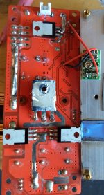
IMG_20180724_073837236_cr_sm.jpg
IMG_20180724_073901789_cr_sm.jpg
 
wturber said:
And while I find the notion of getting a PhaseRunner to be very attractive, that also means I would need to get a CA as well.
You don't actually need a CA to use the PR. :)

Though the PR is pretty expensive all on it's own. :(

The CA is definitely handy for the stuff it does, including speedo / power display, but you can use cheap alternatives for those (I think you already have a wattmeter), and the PR itself has a fair bit of programmable adjustments to it via a PC/USB connection.
 
wturber said:
I tested the output capacitors for shorts and found none. The capacitors seems to act normally in that they showed an initial resistance of about 1kohm that progressively increased as I left the meter connected - presumably because the capacitors were storing charge and hence increasing resistance.

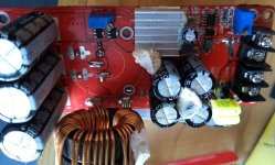
Then they're probably not solely responsible for the problem...but at the least the one with the domed top is failing, and it's likely that all of the ones that are the same value are bad; they tend to fail in batches, even from known-good manufacturers.

It's not as bad as a decade and more ago when the capacitor plague was in full swing, but there are still problems I see in all sorts of electronics that I suspect are caused by similar electrolyte problems, where the electrolyte decomposes and gasses, which often swells the can, or sometimes just outgasses via the rubber seal, but in either case it reduces the functionality of the cap.


Caps can appear to work normally in a test like that, but still have significant leakage/current flow when at higher voltages, in operation.

Same thing can happen with FETs and other semiconductors--a static test appears to work, but they breakdown and act wierd in-use. :/
 
amberwolf said:
wturber said:
And while I find the notion of getting a PhaseRunner to be very attractive, that also means I would need to get a CA as well.
You don't actually need a CA to use the PR. :)

I can't imagine spending the money on the PR and not also getting the CA as well. Even if it isn't strictly necessary, the CA has features I'd like to use and perhaps capabilities that I might use in the future. In for a penny ...
 
amberwolf said:
wturber said:
I tested the output capacitors for shorts and found none. The capacitors seems to act normally in that they showed an initial resistance of about 1kohm that progressively increased as I left the meter connected - presumably because the capacitors were storing charge and hence increasing resistance.
<snip>

Caps can appear to work normally in a test like that, but still have significant leakage/current flow when at higher voltages, in operation.

Same thing can happen with FETs and other semiconductors--a static test appears to work, but they breakdown and act wierd in-use. :/

Yeah - I realize that the test could only positively show a fail and could not positively show the caps are good. Though frankly, at this point, given all the possible fail points, I'm not sure it makes sense to try to do anything with it.
 
Just for grins and possible future reference, the two output diodes at the bottom are:
MBRF20100CTG
Switch-mode
Schottky Power Rectifier
made by ON Semiconductor

https://www.onsemi.com/pub/Collateral/MBRF20100CT-D.PDF

The small Mosfet at the top is a Wuxi NCE Power Semiconductor NCE80H16 (Chinese)
https://lcsc.com/product-detail/MOSFET_NCE80H16_C168804.html

The main power mosfet is also from Wuxi NCE Power Semiconductor NCE85H21TC
http://www.ncepower.com/Upload/MOSFET/NCE85H21TCdatasheet-16543235225.pdf

So I'd assume the ON Semi diodes are pretty high quality but the power rectifiers I'm less sure of.
 
Alan B said:
If the connector was not fully meshed, and generated arcing, the voltages generated by the inductive kickback likely significantly exceeded the ratings of the semiconductors and caps.

... and anybody's guess as to what which would be more likely to be damaged first.

I would have guessed that there was simply a connection through the pre-charge resistor. But who's to say that the connector wasn't close enough to arc to the main contacts or across the resistor? And in my experience, sources of problem are often found by asking the question of "what changes are known to have occurred right before the failure?" BTW, the input side capacitors are not a top tier Japanese brand. They are Chongx and I can't find a lot on that company/brand's reputation.

As a practical matter, it probably doesn't make sense to try to repair this booster. But now I'm a bit curious. I think I'll price some components and go from there.
 
On the blown converter, I suggest measuring resistance across the legs on the FETs looking for shorts. Middle leg is always the drain. From drain to source, a healthy FET will look like a diode. When installed in a circuit, you may be unable to make a good measurement, but usually a shorted part will be apparent.

Caps can fail shorted but usually I find they fail open more often or just lose so much capacitance they can't do their job anymore. I have a meter with a cap check mode that works well for testing these.

It would be nice to know what failed so hopefully it can be avoided with the new one.
 
fechter said:
On the blown converter, I suggest measuring resistance across the legs on the FETs looking for shorts. Middle leg is always the drain. From drain to source, a healthy FET will look like a diode. When installed in a circuit, you may be unable to make a good measurement, but usually a shorted part will be apparent.

Caps can fail shorted but usually I find they fail open more often or just lose so much capacitance they can't do their job anymore. I have a meter with a cap check mode that works well for testing these.

It would be nice to know what failed so hopefully it can be avoided with the new one.

Yes. After 3000 miles, I'm inclined to think that there was more likely a triggering event that caused the failure than a fundamental design or use flaw. It seems to me that if the FET or capacitors on the input side failed, then that probably bolsters the case for AlanB's "arcing" theory as a cause. But I'm not really sure about that. Could failed output capacitors also trigger that kind of failure? Could the FET just fail for no apparent reason? Given that the booster never got hot, it seems unlikely to me that the FET was ever really stressed by normal usage.

I will test the FET as you describe. I was looking at a YouTube video earlier that talked about using the diode testing function of a multi-meter to test a FET. I'm just not sure if my multi-meter has that feature. I don't think it does.
 
The semiconductors are more fragile than the caps.

FETs and diodes generally fail from voltage spikes or die temperature. If it worked for awhile it could be thermal, things like loosening of the FET to heatsink screws, drying out of the thermal paste, hotter ambient temperature or higher current. Loose connections most anywhere in the circuit may create voltage spikes. A careful post-mortem analysis of failed components and a diagram might be used to figure it out. Failure analysis often involves taking the chips apart and inspecting the "die" under a microscope, an experienced failure analysis engineer can look at the die and tell a lot about the failure.
 
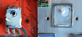
The FET to heatsink connection was still quite good. The thermal pad is still soft and the thermal grease is not dried out. Both screws (one on each side) that clamp the PCB to the sink in that area were still tight. I had to pry up the coil (see photo in previous posting) to get to one of the screws which was still keeping the PCB firmly attached all by itself.

While ambient temperatures have been high lately, the system never turns on its cooling fan and the heatsink is never warmer to the touch than ambient air. I suspect that my placement of the booster on the seat tube with the heat sink facing forward provides a lot of good ambient air flow that keeps everything pretty cool. (And I think this is probably the better way to cool a Phaserunner as well. Reverse mount it with the heat sink facing forward into the wind.) The new booster also has not yet turned on its cooling fan, and I'm biking in temps above 100 deg F. So I think cooling is good since both units don't care to turn on their cooling fans and it seems unlikely that two units would both have failed cooling systems. Also, the max junction temp for the FET is 175 deg C!! And I'm typically only boosting about 12-18 volts which should be a fairly high efficiency range for this booster. So I don't think there is much reason to suspect die heat as the culprit. The only thing I might suspect in that area is whether it made sense to use both thermal paste and a thermal pad. From my CPU experience, I thought it was supposed to be "either or", not both.

IMG_20180724_073837236_FET.jpg
 
Looks like a very poor thermal path. You are right about thermal pad/paste, ideally neither would be used the the metal would be a perfect clamped fit, the pad/paste is supposed to be very thin and only for the part that can't be metal to metal. The pads are a bit thicker, the good ones are very thermally conductive and very expensive, so they probably aren't what is here.

The good airflow may prevent the fans from turning on. The sensors that trigger the fans are probably better cooled than the FETs.

The PhaseRunner does not have fins, it has a metal base that is designed to be clamped to the bike tubes to conduction cool. You can improve it by clamping it to a heatsink.

I don't think you mentioned whether the FETs actually failed.

Typically controller FETs fail either right as the throttle is opened (due to high voltage / high current peaks when back EMF is low), or they fail on a long hard run (heat buildup). The stresses on the booster are at least somewhat similar.

I just reread the description of the failure. So it was very early in the trip, things quit working, and the connector was loose and got very hot, and plugging it in popped the fuse with a short in the converter.

If the input connector was adding extra resistance this could cause the voltage ringing on the FET to be larger than normal, and generate higher peak voltages that could punch through the FET's internal oxide insulation. There is very little margin there. The signals around the FET are not pretty, and the ringing puts voltage peaks up considerably over the supply voltage. With increased resistance in the circuit the ringing can rise to even higher values. Or it could be the FET is being overstressed all the time, and it just chose that moment to let go. I've had a controller that would go for months and then fail.

I think you've had pretty good life out of this booster in this stressful application. Others who have tried it generally blow them out quickly. Yours lasted awhile.
 
Another common failure mode is the capacitors going open or drastically losing capacitance. This can then allow voltage spikes to kill the FETs or other parts. Sometimes you see the caps actually explode or swell up.
 
Turns out my meter does have a diode test function. So I tested the FET installed and it was shorted across all gates. I removed it and it tested the same. That's clearly a problem if not THE problem. Ordering just one will probably be difficult. If I can order one at a reasonable cost I'll replace the FET and the output capacitors and see if that fixes it.

Regarding heating/cooling and sensor.
The sensor is installed on the heatsink and adjacent to the main FET and on the same (back) side. But no thermal grease or pad is used. The sensor is a small PCB screwed directly to the aluminum. That seems sub-optimal for conducting heat from the sink since the PCB back is not metal. But the sensor does seem be receiving the same cooling as the FETs - though possibly not the appropriate heating.
That said, I checked my working booster after a slow hill climb (14% grade) at about 650 watts battery draw and the heat sink temp was about 15 degrees above ambient at 116 deg F. My headlight was hotter at 120 deg F. The motor was actually cooler at 110 deg. F - presumably the heat hadn't yet been able to migrate to the case.

The FET's heat thermal pad was thin and made of fabric encapsulated in a gray rubber-like compound - presumably silicone. With two screws sandwiching the main FET between the heat sink and PCB, it seem to me that the FET is making as solid or more solid contact with the heat sink than if a single screw had been used. This is more like the way that most CPUs are pressed against a heatsink.

The other small FET and the two Schottky diodes used thicker pads - presumably because their cases are thinner and hence won't tend to press as solidly against the heatsink.

The sequence prior to the fail was to the best of my recollection:
1) Re-connect power connectors.
2) Power on LCD and set PAS level. (All appeared normal)
3) Walk bike a few feet and procede to ride
4) Bike stutters and LCD blinks out (maybe back? Can't be sure.)
5) Check connector - its hot!!
6) Separate connector, do visual inspection, smell, wait a minute or so.
7) Re-connect resulting in both 20 amp fuses on the booster popping immediately!
 
fechter said:
Another common failure mode is the capacitors going open or drastically losing capacitance. This can then allow voltage spikes to kill the FETs or other parts. Sometimes you see the caps actually explode or swell up.

One output capacitor is slightly domed. Amberwolf has strongly suggested considering all three as effectively failed.
 
Alan B said:
I think you've had pretty good life out of this booster in this stressful application. Others who have tried it generally blow them out quickly. Yours lasted awhile.

I never found examples anywhere online of someone using one of these 1500 watt or 1200 watt boosters on an e-bike. I searched a lot. All I found was a guy using I think a 600 watt booster (wrong - he used a 1200 watt booster) on his 36 volt 250 watt e-bike. And that worked fine for him. No longevity report as I recall.
 
Most uses I have seen of various inexpensive voltage boosters is, as I mentioned before - for battery charging. There were a number of those, and a lot of failures.

The thing to check is FET temperature, and the differential between FET and heatsink. If you can.

As fechter mentioned, the capacitors are key to manage the voltage spikes. As the capacitors weaken the spikes increase. Caps heat up due to ripple current and ambient temperature. They are very poor at dissipating heat, and it shortens their life dramatically. You might consider using more caps (in parallel), and better caps to improve that. Lower inductance and ESR, higher temperature, and higher capacitance would all be good. If you have access to a scope you can see how well the circuit is managing voltage spikes.

The FET should not be hard to substitute with a better one. Lower on resistance, equal or higher voltage ratings and similar or lower gate drive.

The temperature sensing would best be on the FET rather than the heatsink, and as you discovered it doesn't have a low impedance thermal path anyway. Good airflow will probably keep it off, so no surprise the fans don't run. But they probably don't need to.
 
Because the FET is sandwiched between the heat sink and the PCB, there is no simple way to check the temp. I'd need a temp probe or a thermistor tucked down next to the FET.

I'll look into finding upgrade replacement parts and post what I find here. It seems to me that the new booster has down graded ouptut caps since they dropped from 680uf to 470uf and are physically smaller. I have no access to a scope. Though I do see some hacks for turning an android phone into a scope. Though most of the YouTube videos on the subject seem to be made by guys who are unaware of the existence of tripods - which does not instill confidence.
 
Back
Top