Why is my Panasonic Li-ion battery not charging?

pvdm

10 mW
Joined
Feb 6, 2013
Messages
25
Hi All
My partner has a Panasonic 24V 12Ah Li-ion battery on her Montego 200W Ebike. The bike was cutting power regularly during hill climbing so I did (what seemed like a conservative) shunt mod on the controller. The bike was going much better after this mod and we were quite happy with it for about a month. I do not know if it is related to this mod but all of a sudden about a month after doing the mod, the battery will no longer take a charge. The battery charger is just a simple transformer type with a green LED for when it is not connected or has a full battery and a red LED during charging. The battery still has 25.5V and only drops to around 24.5V under load which indicates that the battery is low and needs charging, but it is not dead. The charger is putting out 29.7 V which is correct for its specifications. When I put a multimeter on the charging socket on the battery I get no reading at all (0V), is that normal? I opened the battery and all the connections that I could easily see seem to be intact and in good condition. The bike still runs fine, it just will not charge.

Does anyone know what could be happening? Can the BMS shut down the charging circuit like this if, for instance, current draw is too high?
 
pvdm said:
Can the BMS shut down the charging circuit like this if, for instance, current draw is too high?


Probably not from current draw.

It can stop charging if there is a big imbalance in the cell voltages (i.e. unbalanced). Sometimes leaving it on charger for a day or two can allow the BMS to bring the cells back to balance.
Or a cell may have died from extra stressing after the shunt mod? Or the BMS overheated and died.
Or a connection/tab failed inside the battery.
Or a hidden fuse?

Since the charger seems fine, I would start with a visual inspection of cells and measuring the individual cell voltages.
 
Thank you Gregory
I have plugged the charger in for another night on charge and will see how it goes. I have already tried for 24 hours, but I'll try longer. The battery BMS has temperature protection, current protection, and high and low voltage protection so I am hoping it should have been smart enough not to become damaged. Do you think I should be seeing battery voltage at the charging socket? Next ill try measuring the individual cell voltages, but does it not suggest that the battery is fine if under load it is not dropping below 24V?
 
My guess is a broken wire , quite possibly in the plug, on the charger input to the battery.

There usually is not a bms shut off function to the charger wire, but it could be a fault in the bms if you don't find an obvious disconnection on the plug wiring.
 
Thanks Dogman
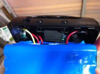
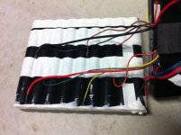
I had a look at all the connections and they all seem to be in good working order, although I would need to really rip into this battery to do a thorough test. Can anyone identify which wires to probe in the attached pictures to measure individual cell voltages? In the first pic, the two thick red wires go to the 10A fuse (which is not blown), the two yellow wires are for the on/off switch and the paired, thin red and black are for the charging socket. The thin blue and black seem to be for the battery capacity display that you can see on the left in the second pic. In the second pic a lot of the wires terminate in the BMS that is enclosed within a black box that cannot be opened without breaking the plastic. I am pretty close to binning this battery and making a Hobbyking LiPo pack.
battery3.JPG
View attachment 1
 
if you decide to throw it away i will pay postage to take it apart if you won't. unless the postage is too much i guess.

not sure why you said you have to rip it apart. i just cut the plastic sleeve down the middle with some scissors so i can put it back on later.

you only have to measure the cell voltages at the BMS where the wires go in to the pcb. maybe later you might have to open the plastic case around it if we cannot figure out what died. i assume you have checked continuity on the fuses and wires.
 
Thanks dnmun, I live in Australia, so I imagine the postage would be pretty expensive to the US. Yes, you are right, I should just cut the blue plastic off to get a better look at where the wires are going. I am very new to ebikes so I was a little hesitant but will happily do this if its necessary. The fuse is fine, although I have not tested the wires leaving the fuse. It gets correct voltage (25.5V) at the output to the controller (right hand side of second pic) when power switch is on. Interestingly, I measured 4V between the thin red and black wires also at the output socket but these are not controlled by the power switch. Not sure what that 4V is for though...
 
pvdm said:
Can anyone identify which wires to probe in the attached pictures to measure individual cell voltages? .....


........ a lot of the wires terminate in the BMS that is enclosed within a black box that cannot be opened without breaking the plastic.

Measure cell voltages either at the BMS where the 8 little wires connect or at the cell where the wires connect. Whichever is easiest to access. Wires are connected to the ends of each cell group so the BMS can sequentially measure each cell voltage. So that's what you do, measure between wires 1 &2, 2&3 etc
 
yep, start by measuring the cell voltages. measure the cell voltages while charging it too in case they show different numbers.

with scissors you can put one leg of the scissor under the plastic and pull it up enuff to clear the wires underneath before you cut. cut right down the middle and later you can fold it back over the pack and tape it down.

sometimes plastic cases such as what you say encloses the BMS will have little hidden plastic catches hidden behind the seams and they can be opened with a credit card or guitar pick inserted in the seam to pop the plastic catch back out of the hook spot.

but a screwdriver with a sharp point works wonders. don't stick it in your hand though.
 
Great thanks guys, I will remove the blue plastic and investigate this tonight. Hopefully the BMS case clips together/apart, although there are no seams in the plastic where the wires go into the case. Never mind, Ill investigate and let you know how I go. Cheers!
 
Looks hard to get at the bms to measure there. Look for broken or disconnected thin wires to the bms when you have it unwrapped. If all looks good with the cells themselves, it could be a disconnected wire inside that bms box.

Confirm with a voltmeter, that the current does pass through the plug to the charger. With the charger unplugged from the wall, you should detect battery voltage on the charger side of the plug when you plug in the charger to the battery.
 
Hi again
So I have opened the battery sheath and tested the cell voltage at the BMS. Each cell that I could measure was exactly 3.6V but I could only measure 6 cells. The battery should be 7 cells from what I can gather. In the attached pic you can see there are 6 balance wires of all different colours. Anyone know why there would be only 6 balance wires? Other than the balance wires there are two thick power wires and two double thin, red and black wires. Both of which show battery voltage. Can anyone tell me what the configuration of the cells could be? There are 36 individual cells that I can see but I don't know how this can be arranged to become 7 cell??

image.jpg
 
dogman said:
Looks hard to get at the bms to measure there. Look for broken or disconnected thin wires to the bms when you have it unwrapped. If all looks good with the cells themselves, it could be a disconnected wire inside that bms box.

Confirm with a voltmeter, that the current does pass through the plug to the charger. With the charger unplugged from the wall, you should detect battery voltage on the charger side of the plug when you plug in the charger to the battery.

Thanks Dogman
When I plug the charger into the charging port on the battery I get 29.7V at the BMS. (29.7V is what the charger puts out unconnected) So that rules out the charger as being faulty as far as I can determine. Do you agree?
 
there are 6 sense wires and you measure the last or 7th cell between the top sense wire and the red wire. or maybe you did not measure between the black wire and the first sense wire.
 
pvdm said:
There are 36 individual cells that I can see but I don't know how this can be arranged to become 7 cell??

You already have the answer. 36 is not a multiple of 7. So you don't have a 7s pack. You have a 6s pack, 22.2V nominal, 25.2V max.
How do you know it's Panasonic? There is no reason to cover those cells with that black stuff. Very fishy.
 
I think you have a 7s and need to do as Dnmum said as testing the first or last cell. One led has of go to the neg. to the first wire or pos. to the last wire. Do yourself a favor and write it down on paper.
 
999zip999 said:
I think you have a 7s

But he says there are 36 cells.
And If the charger is 29V I can't figure it out from that picture.

I think you still need to pick away at the wrapping, inspect the tabs on the cells and the wire solders. And put us out of our misery as to the pack config.
 
Hi again
Well I said I was new to all this so, well I made a mistake. There are only 35 individual cells. One of the black plastic case locations was empty inside. So the cell configuration is 7s5p. The pic shows the BMS and even though there were only 6 wires entering the BMS the two red wires on a sepperate plug gives the final cell voltage. So 4 of the cells were at 3.6 and 3 cells were at 3.7 and that makes up the total battery voltage that I am measuring at the moment of 25.5v. Still no idea why it is not charging. I have a 8s lipo charger. Do you think I should try using this to charge and balance the battery and get rid of the standard BMS?
 
you measured a voltage on the output of your current charger so i doubt if that is the problem.

if you take a picture showing the top and bottom of the BMS so we can follow the traces to see how it is wired up we can give some advice about where to measure the voltages inside the BMS.

i still think you have a bad fuse or connection in the charging wires. so you need to see that voltage on the BMS, beyond the fuse.
 
pvdm said:
Do you think I should try using this to charge and balance the battery and get rid of the standard BMS?
It's ALWAYS a good idea to trash the BMS. None of the existing BMSes work. All they do is give you the false security feeling that the battery is protected. Nothing is further from the truth.
 
SamTexas said:
pvdm said:
Do you think I should try using this to charge and balance the battery and get rid of the standard BMS?
It's ALWAYS a good idea to trash the BMS. None of the existing BMSes work. All they do is give you the false security feeling that the battery is protected. Nothing is further from the truth.

While I'm a huge fan of using a good BMS, I do agree that the ones installed on these cheap batteries are woefully inadequate.

I've burned up so many of those cheap things.

It might be worth looking into getting a set of Methods boards. They're not cheap, but they'll probably outlive the battery, and prevent disaster.
 
grindz145 said:
While I'm a huge fan of using a good BMS, I do agree that the ones installed on these cheap batteries are woefully inadequate.

I've burned up so many of those cheap things.

I'm still searching for a TRULY WORKING BMS. Sounds like you have at least one "good" BMS. Which one is it? And exactly why you think it's good?
 
dnmun said:
you measured a voltage on the output of your current charger so i doubt if that is the problem.

if you take a picture showing the top and bottom of the BMS so we can follow the traces to see how it is wired up we can give some advice about where to measure the voltages inside the BMS.

i still think you have a bad fuse or connection in the charging wires. so you need to see that voltage on the BMS, beyond the fuse.

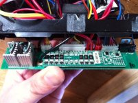
So here are some pics of the BMS. I'm always amazed that anyone can look at these and work out what is going on! :)
There are two PCB directly on top of one another so I imagine you may not be able to trace the imput lines?
The input lines are : yellow yellow plug is the power switch, six multicolored are the balance wires, double black and red with a blue and black plug are the charging wires and for the capacity meter. Double black plug and double red plug give the final cell voltage and the negative for the cell voltages.

image.jpg
 
it gets a little familiar after you look for the basic units. those two transistors standing on end with the heat sink are how the current flows from the battery to the controller. they are mosfets and they are turned off and preventing you from charging, if it is not the fuse.

they turn off when something is wrong with the battery to keep you from damaging the battery. they are kinda expensive so the BMS is like insurance.

i followed what you said about the wires, on the far right is a three terminal device, a transistor or voltage regulator. can you read the part number on it?

you can put the black lead from your voltmeter on the negative terminal of the battery and then use the red one and measure the voltages on the opposite end of those surface mount resistors sitting on the flying bridge. to make sure the voltages get to that point.

they use the color code for the sensor wires too black brown red orange yellow green then red for the top of #7.
 
Hey Mate there are a couple dozen who can read that BMS on the forum Dnmum is the only one who will help trace it.
If a chicks bike and and plug and play you need a BMS. I don't run one, but if some one else's it's a most always a must.
 
Back
Top