Why is my Panasonic Li-ion battery not charging?

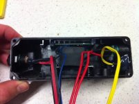
i am thinking the two small black wires together next to the two red wires together come from the fuse and from the charger positive? and the black wire is from the charger negative? and the blue wire next to it does what?

so i think that device in the corner may be the charging mosfet, where do the two black wires in the far outside plug go? to the thermal circuit breaker?
 
dnmun said:
it gets a little familiar after you look for the basic units. those two transistors standing on end with the heat sink are how the current flows from the battery to the controller. they are mosfets and they are turned off and preventing you from charging, if it is not the fuse.

they turn off when something is wrong with the battery to keep you from damaging the battery. they are kinda expensive so the BMS is like insurance.

i followed what you said about the wires, on the far right is a three terminal device, a transistor or voltage regulator. can you read the part number on it?

you can put the black lead from your voltmeter on the negative terminal of the battery and then use the red one and measure the voltages on the opposite end of those surface mount resistors sitting on the flying bridge. to make sure the voltages get to that point.

they use the color code for the sensor wires too black brown red orange yellow green then red for the top of #7.

Thanks Dnmun
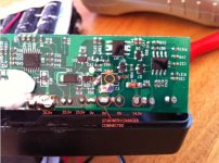
I'm not exactly sure which part you mean on the far right of the underside of the PCB "Three terminal device". I'll attach some more pics that might help. I have measured the voltage on the resistors of the flying bridge and they are the same as the multicolored sense wires, so 3.7, 7.3,10.9,14.6,18.2,21.8 the first one next to the aluminum heat sinks has no voltage at all. When I plug the charger into the socket I get 29.7v on the pins on the underside of the PCB where the double thin red and black wires plug in. The large fuse is inline with the thick red power wire before the connection to the controller. The thin blue wire goes to another small PCB that seems to control the battery level gauge. I'll take a pic of that also.

image.jpg


Dnmun, Is this the voltage regulator you were talking about? The part number is F3205Z P108D U4Y9
 
no, that is the charging mosfet. it is a international rectifier 3205 mosfet. after i put together what you said about the double wires to the charger and saw it connected to them i realized it was the charging mosfet, not the others on the output mounted in those heat sinks.

the fuse between the big red wire and the controller is for the battery output. we want the one that is in the charging line. it will be around 3-5A.

i called it a three terminal device because it has three legs. when you look at the mosfet from the front. there from left to right, the gate leg, the drain leg, and the source leg.

you are going to measure the voltage on the gate leg. use the 20V DC scale on the meter, put the black probe on B-, the big black wire to the battery which connects at "out-" over on the left side. that is the battery ground. i think. put the red probe on the gate leg next to where that orange diode is connected. just stick the red probe into the solder where the gate leg is soldered to the pcb.

once we know if that mosfet is active or not then we can guess more.

even though the pack is open, it is still charged so be careful not to short stuff.

for this measurement everything has to be set up normally, and you can put it on the charger to pretend to be charging when you measure.

if the charging mosfet is off we will look for one thing, and if it is on we will look for another problem. so closer to fixed, we should be able to fix it.

the mosfet doesn't look burned up. but even if it is, they are cheap and someone there will have some spares and can mail one of them to you.
 
Thanks Dnmun
I appreciate your help with this. For me there is a lot of satisfaction in learning how these things work, so thanks a lot.

I measured the voltage on the gate leg of the charging MOSFET and it was 14.16v when the charger was connected. So I guess that rules out the small fuse in the charging line, unless it is downstream of the charging MOSFET.
 
i like to figure things out too. but you have a problem and it can be fixed. we just don't know what the problem is.

but your measurement did basically prove that the BMS is working normally. nothing is wrong with anything except the connection from the charger to the battery. the charging mosfet is turned on and functioning properly.

to explain: the voltage you measured on the gate is generated on that pcb. it comes from the top of the 4th cell in the pack and it turns the charging and discharging mosfets off and on. since that voltage is present then the mosfet is on, and it should be charging.

i can see where the trace runs off from the drain (center leg) of that charging mosfet, but cannot see where it ends. it goes by that "10" and right across the edge to the output mosfets i think. it should go to the drain of the output mosfet over there on the other side in the heatsink. if that mosfet, the output mosfet is turned off then that current for charging is stopped at the output mosfet so it doesn't charge.

you can measure the gate voltage on that mosfet by finding the trace that runs over to those mosfets to the gate. the source leg of those mosfets will be soldered into the big wide trace that goes to the battery B- and it is labeled out- there.

the gate lead is the trace that runs from that little transistor just above your finger there and runs to the left over to the mosfets. double check to confirm and measure that voltage too. if they are both on then it is a connection problem and nothing is wrong with the BMS.

but check that first and then we can check continuity from the charger to the pcb. but that involves using the voltmeter to check the continuity and can damage a voltmeter if done in an active circuit so we gotta figure that out then.

first, just measure the gate on the output mosfets now. you might even be able to reach the gate leg itself through the white goop.
 
Great, thanks again Dnmun. Yes you are absolutely correct, the center drain pin on the charging MOSFET goes along the top of the PCB and to the first output MOSFET. I can not see which pin it goes to though. I have measured the gate (left) pin on the output MOSFET and I get 14.5v there but only when the power switch for the battery is on. When I'm charging the battery it is normally in the off position so this output MOSFET would also be off. There is always 0v at the drain (center pin) of the charging MOSFET and 0.06v at the drain pin of the output MOSFET. I also measure 0v at both source pins.
 
and it does not charge whether you have the power on or off? that is good that you have voltage there on the output mosfet gate. the drain and source legs of the output mosfet are in the battery ground lead so there is not any voltage to expect on the drain or source.

if you go to the spot on the pcb where those two red wires plug into the pcb, those two wires come from the charger as i understand. if you unplug them you should be able to measure the charger voltage on those two red wires. with the black probe on B-. it should measure the full 25.55V or so.

so check that while you have it on the charger. but unplug it to measure so we don't measure the voltage from the battery itself. in fact with the plug disconected from the battery you should see the full 25.55V charger voltage there on those two red wires.
 
Yes I have the full 29.7v at the PCB. I disconnected the plug going to the charging socket and measured 29.7v at the plug and also once plugged into the PCB I measured it at the pins of the plug. So the voltage from the charger is getting to the PCB.
Regarding your other question, no it still does not charge when the power button is on. Still have a green light on the charger and battery voltage is staying at a steady 25.5v.
 
the two red wires from the charger have charger voltage? with the black meter probe on the B- terminal?

the plug on the pcb has the battery voltage? should not be the same voltage when they are disconnected.

so if current flows through the red wire and the mosfets are turned on then it should charge. unless the circuit is open in the ground leg. maybe in the charger plug. but should not see the charger then if that ground is open.

you should see that 25V battery voltage at that plug where the two red wires connect. when the two red wires connect then the voltage will be the same on both. it should be 25V if that is what the battery is at.
 
Thanks Dnmun
I realised that my last post was not very clear, sorry about that. Yes, the two red wires from the charger have charger voltage (measured with the negative probe on the B- and positive on the charging wire positive pins), but when the charger is not connected I get 0v with the same measurement. It sounds like I should be getting battery voltage with this second measurement, but I am not.
 
no problem. makes sense. to the left of that plug where the charger wire comes down are two red wires. one goes to the controller and one goes to the top of the battery?

the one that goes to the top of the battery is not connected to the top of the battery i think. if it was connected you would see battery voltage on that wire, and it goes right across to that plug i bet. should be one continuous fat sized trace along the edge of the pcb, so no current on the positive side is going from the charger through that connection there on the pcb to the battery.

find that open circuit and you can get it charging again. i think that is where they go. you can confirm where they go.
 
Thanks Dnmun, I think we are getting pretty close now. The double red wires that you refer to, both lead directly to the battery pack. They have battery voltage (25.5v). The other two red wires that lead to the charging port has 0v or 29.7v when the charger is connected. What is the component that I have circled in yellow "F2"? The part number that I can make out on the top is "12AH3 SC SF". At the top of it I have battery voltage, the bottom leads directly to the charging positive wire. The sides are both 13.2v. It seems to be the link between battery voltage and charger voltage and might be stopping the charge voltage getting to the battery. EDIT: that should say "29.7V when the charger is connected" on the picture.
photo_edit.jpg
 
that's the fuse i was asking you about originally. pretty fancy. that is a 12A fuse that is triggered to burn out by the control function if the cells reach overcharge. it is there to prevent the battery from being damaged. that's what i think it does anyway. and why there is 13V there. maybe.

if you can find a small 15A car fuse, with the two spade legs then you can solder the new fuse on top of that fuse. actually the fuse can go from one side of that present fuse where there is battery voltage all the way over to where the two wires are soldered into the pcb on the edge there where it says 27V when charger connected. same thing as soldering just across the fuse, and the legs may fit then, or a 5x20mm fuse may just barely fit across there and you can solder it on each end to that space.

the legs may be too far apart though so if not we can put a wire there and put the fuse somewhere else in the line. but if you short that out with a wire you should see it charge. there may or may not be a good reason for the fuse to blow. so be careful if you put a wire jumper back there, even temporarily. way cool.
 
Ha ha, so that's a fuse hey? Well I have never seen a SMT fuse before so there you go. Thanks for your patience, I suppose that's kinda obvious in the end! Why it blew is another story though. I shorted out the solder between the top and bottom of the fuse and the charger started charging so I guess that solves it.

I have a 8s Lipo charger and I am wondering if I use that to charge it and set the upper voltage limit slightly lower to be on the safe side and set the charge current at 1.5A, which is the same as the factory charger, would that be a safer/better charger?
 
Hey All
Have been thinking about this problem for a few days. Given that this fuse is programmed to burn itself out if some preset limit is reached, then replacing it with a traditional fuse will basically be the same as simply shorting it out with a wire, as the traditional fuse will never blow simply by high current. Is that right or have I missed something? I cannot track down a replacement fuse such as the original and a replacement original BMS seems difficult to track down also.

So, I am thinking of running a jumper wire over the fuse and hopefully this will only affect the overcharge function of the BMS and all other functions should work normally? Thoughts/opinions?
 
not a given that it is programmed to burn itself out.

i assumed that the fuse may have some type of element that can be burned open if the charging mosfet fails to stop the charging. the charging mosfet could be shorted and if the BMS detected HVC on one cell then when the BMS turns off that mosfet then it would continue to charge. i speculated that this fuse would be forced to open when the cell voltage reached a higher level of the HVC and sent a current out where you see the 13.6V that caused the fuse to open. all assumed.

the risk is that the charger lead can be shorted to something and the battery can discharge back through the charging line into the short and it would cause a fire. there is no circuit element to detect a short when the charging lead is shorted. if the output lead is shorted then the BMS will turn off the discharging mosfets, but the charging lead to the battery is not protected.

i think you should use a fuse across there and it would help to know whether that function that may have caused the fuse to burn open is now still conducting current. maybe the fuse blowing current is now latched on permanently. so knowing how that circuit delivering the 13.6V works will help.

it doesn't have to be 15A or 12A like is there now. it could be 10A or even just 5A since your charge pushes less current than that. but it should be fused imo. but in most batteries it is not fused so it would not be an unusual design if there was no fuse. but there should be. this is the one place i recommend people add a fuse but no one ever does. they all put the fuse on the output of the battery even though the BMS protects the battery from short circuits.
 
Ok great, I understand the function of the fuse now, cheers. I have soldered in a 5A fuse. I remote mounted it and just ran the wires to the pins on the PCB. I have plugged it in and it seems to be charging as per normal. No flames so far so I suppose that's a win! I'll leave it charging for a couple of hours and see how the cells balance.

One other quick question, do these cheap transformer style chargers monitor the cell voltage and ramp down the charging current as it gets close to fully charged? Or do they switch off completely when a set voltage is reached? I am just wondering if it could have been the fault of the charger leading to the overcharged condition.
 
yes, you don't wanna use a high voltage much above the normal fully charged 4.2x7 volts. but the fuse is really only there as a back up, fail proof, method of turning off the charging current if it detects a cell above the normal HVC. so it is there to protect against failure by shorting of that charging mosfet, the 3205.
 
Back
Top