yet another solderless DIY battery pack via NIB's

radad said:
I used georgiacopper for copper sheets. Get 12x12" sheet, a tin snip and DIY. I used a 12x12x.022 my bad, should have used the .012 thk.
I been looking around the web on copper sheet thickness and I found this pretty cool comparison web page.
http://basiccopper.com/thicknessguide.html
I was thinking the 8 MIL (.008 inches thick) looks pretty good.

[youtube]_EtZE7oQJaw[/youtube]


radad said:
I been waiting for some of the rocket scientist members here to tear up this idea fast. Heat, weight, eddy currents,cost etc. PLEASE CHIME IN EGGHEADS! Yea I'm adding around 25-30 ozs weight penalty and 50 cents to a 6 dollar battery. But for the ease & flexibility it will be worth it.
Well you got LFP interested so I don't think it can be cut to pieces in theory.
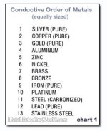
18650s are always encased in steel (anything else and you could crush them too easily and become dangerous) as clearly stated here https://ntsworks.com/battery/battery-technology/
Steel sits a the bottom of the chart so if there is argument against using even nickel then maybe they should take it to the folks who designed the 18650 cell.

conductive_order.jpg

Other thing I wonder about is it worth buying the higher magnetic strength rated nib magnets, n35 is a good starting point but I noticed n42 isn't much more in cost, more about ratings here http://www.kjmagnetics.com/neomaginfo.asp
 
Great thread. I like the idea of DIY modular battery holders designed to accommodate the magnets also.
 
Endless sphere rocks. Looks like enough people are interested in this idea. I posted this idea here in hopes of getting some tech help. I got a lot more questions than answers! I'm good mechanically but I have limited electronics knowledge. I could do a 3d model for a 3d printer but there is a lot more info to sort out first.

Like how much current a specific size neodymium magnet can carry based on its plating chemistry and thickness before it heats up to much. I'm guessing that someone here would have the equipment to setup a circuit to feed variable amps through say a 12x3mm neodymium and monitor the temps. With my finger as a temp probe and cheap $20 multimeter my tests here at home are more of a guessing game than scientific. Whats the best plating ni-cu-ni, ni, au, even zinc plating is avialable, slightly more conductive then nickel but not as thick plating.

Whats the best material/thickness for the bus bars. I originally thought the bigger copper strips would add some cooling effect to the magnets attached to the batteries and give lower resistants, is that even necessary, or at what amps would it needed?

Even cooler idea is if the magnets could somehow act as a fuse. ie when they heat up to much and lose their magnetism it opens the circuit somehow.

LFP???
 
radad said:
Whats the best plating ni-cu-ni, ni, au, even zinc plating is avialable, slightly more conductive then nickel but not as thick plating.

Whats the best material/thickness for the bus bars. I originally thought the bigger copper strips would add some cooling effect to the magnets attached to the batteries and give lower resistants, is that even necessary, or at what amps would it needed?

Even cooler idea is if the magnets could somehow act as a fuse. ie when they heat up to much and lose their magnetism it opens the circuit somehow.

LFP???
L F P is "live for psychics" member, in theory he should be able to argue against anything that is physical.
I read this interesting article about soldering nib magnets and how it's not really a practical thing to do, interestingly high heat permanently kills the the magnetic strength of nibs, so its important to avoid heat.
http://strong-rare-earth-magnets.com/soldering-rare-earth-magnets-the-blistering-truth/

Electroplating the nibs with copper might help, looks very easy and cheap to do as well. https://www.youtube.com/watch?v=1goL4h6UHXo

I think a good way to attack heat problems is via increasing conductivity of the 18650 cell steel side of things since it's a lot tougher and designed to be welded to etc, one idea I had was to somehow tip the metal interfaces of the 18650 cells with copper so they greatly increase there electrical conductivity, unlike plating the nib I don't know the ideal way to achieve that though.

I guess the other question to ask is while copper is one of the best conductors of electricity does it mean that its also the best at conducting over a surface area that isn't physically attached/welded together? Maybe there is another metal that is some how magically better at allowing electrons to jump across, I was thinking that it might be logically the softer the metal the better it is at allowing electrons to jump across non welded connections, this might be why car batteries use lead terminals despite lead being one of the very worst metals in electrical conductivity. This can add to the theory that getting an ideal thinness of copper sheet between the magnets can help form a flatter more conforming level of contact between the connections, or maybe just gently hitting each connection point with a hammer might give the same effect.
 
I think lead for LA battery terminals is used simply because the plates and internal connections are also lead, so it saves joining dissimilar metals. It's also corrosion resistant.
 
TheBeastie good info ! THX
I think your right on, thinner material can make better contact. Softer and flatter can help too. Just like extreme pc overclockers (me) used to do - wet sand cpu & heatsink down to 600 grit on a piece of glass to insure flatness for better heat transfer. Flatter = more contact area, maybe more so than softer. copper is soft to sand flat and stay that way, but aluminum can be. Zinc looks like a good candidate too, both conductive and soft. But I keep going back to nickel its conductive and magnetic.

The Mohs Scale of Hardness for Metals
hardness grades for common metals
Lead: 1.5
Tin: 1.5
Zinc: 2.5
Gold: 2.5-3
Silver: 2.5-3
Aluminum: 2.5-3
Copper: 3
Brass: 3
Bronze: 3
Nickel: 4
Platinum: 4-4.5
Steel: 4-4.5
Iron: 4.5
 
The thinner (12 mils) copper works great! now I don't need the magnet on the battery terminals, just on the outside of the bus.
I finally feel confident enough to assemble the entire pack. A little scotch tape on the outside of the bus and the magnets don't see any current. Got some 3/8 x 1/8" n45 magnets coming soon this is the last piece of the puzzle.


The standard 18650 battery holder not good for this idea. So heres my idea for a new holder.


I'm getting prices on the 3d printing today, may have this whole thing wrapped up soon!
 
I've subscribed to this thread, please keep us updated with your progress as I'm also researching ways to utilize my 18650 batteries without soldering or welding. Any worries about large jolts while riding causing the magnets to come loose? Especially on the underside of the pack?
 
radad, the setup in your photo looks much more workable :)

Could you take resistance measurements of the cell to copper strip joint?

I would suggest using a dab of flexible adhesive (perhaps polyurethane) and then applying heatshrink over the module. That should keep the magnets securely in place :)
 
radad said:
The thinner (12 mils) copper works great! now I don't need the magnet on the battery terminals, just on the outside of the bus.
I finally feel confident enough to assemble the entire pack. A little scotch tape on the outside of the bus and the magnets don't see any current. Got some 3/8 x 1/8" n45 magnets coming soon this is the last piece of the puzzle.

The standard 18650 battery holder not good for this idea. So heres my idea for a new holder.
I'm getting prices on the 3d printing today, may have this whole thing wrapped up soon!
Looking good Radad, that your new 18650 battery holder design looks pretty radical cool. Can't wait to see it in action.
So 12(mils) copper works better, interesting and yet makes sense.

I made a small video of to demonstration the magnetic strength of neodymium magnets on 18650 cells (and to test out my new camera phone). Test used a decent sized neodymium magnet on Trust-fire then a Sanyo 18650 cells against my sheet of copper. The trust-fire has a noticable amount more magnet pull as I was able to hold the whole sheet up against the edge of the copper sheet, probably because its deliberately designed to be more steel then actually battery. Sanyo could only hold it via the middle.
The end of the video is just me unboxing my copper sheet I got from ebay, dimensions are 0.2mm x 200mm x 1000 mm.
I ordered some cells from fastech so it will be around 10 years before my pack is built.

[youtube]O2aoyt6arWg[/youtube]
 
This is the final version of my battery holder I wanted 3d printed


Its not happening because prices ranged from $275-400 in abs plastic. I could just about buy a 3d printer for that much. I could get it done a lot cheaper in pla plastic but don't think that would hold up to well. Also a little cheaper too for printing the whole thing in one piece, but I want modular.

Anybody willing to print this for me @ material cost? I can send the stl file.

Meanwhile this is the best I can do with the 18650 battery holders:


As you see there are two magnets on each terminal. On the bottom is a 13x1.5mm n35 nib which is held concentrically on the battery by the battery holder itself, so the bottom nib can't slide around. Above it is a 3/8 x 1/8" n45 nib for clamping power and added height for the foam to hold down. Total of about 7 lbs of clamping force between the two nib's! The foam is only so they don't slide around. The copper is 8mm wide by 12 mils thick and fits nicely in the battery holder. Should be good for 30amps + according to http://www.referencedesigner.com/cal/cal_06.php

Also note the danger involved in assembling this. The above pic don't show the series connections, but once there made you better have the bottom secured tightly and be as careful as hell! one wrong move can create a giant short. I placed a rubber mat on either side of the parallel row I was connecting with the nibs. Its almost like working on a bomb. This is not for the faint hearted, or the inpatient, or those without near steel fingers and a very steady hand.

Also I gave up on the scotch tape on the copper toward the nib side. I don't think its needed. While the nib's are seeing voltage, their really not conducting any current, and don;t seem to be heating up.
 
I thought up the other week while watching my kebab/souvlaki being wrapped up in foil and plastic at a fast food place.
I put a nickel strip through a shrink tube with the nibs on top, then cut holes underneath the nickle strip to make contacts onto the cells.
This way entire strips can be held in place and without fear of the magnets jumping to any other places to cause shorts etc.
Also by using shrink tube you could identify any hot spots after use because the tubing will shrink.
I don't have any 18650 cell holders or many cells atm so you have to use your imagination for a entire pack.
 
Interesting thread.
Copper yet corrodes easily on the surface. So the contact will perhaps not be reliable over time? Humidity: green verdigris blossoms. Oxygen: becomes tarnished with black copper oxide.
Nickel and nickel dominated alloys are much much better for contacts. Thats why nickel is used for battery poles of (changeable) batteries, for power plugs etc and for the conductive NIB magnets itself which are often used to create button tops on flat top 18650 cells for e-cigs etc. So the same nickel (covered steel) strips which are used for welding may already be a good choice.

Perhaps the setup gets more robust when the nickel strips are welded to the nickel covered NIB magnets, so that there is only one & direct magnetic (re)movable contact between the cell pole and the link system. Cleaning of contacts mechanically and with ethanol before applying the magnet contact, ...

Whatsoever, I think of central importance really are some milliohm resistance measurements of the contact, and to watch it over time and through mechanical stress. That is a 4-point measurement. Its not really complicated, and can be done with a normal multimeter: For example simply send about 0.2A .. 2A with a power supply unit or charger (in charging direction) through the contact (and through the cell), and measure the millivolts drop over the NIB-cell contact and also over the whole path through the NIB to the link strip (the resistance of the NIB itself should be very small).
Without a power supply even the cell itself can be used for current generation: discharge via a R of about 10 Ohm (when one cell is involved) to create the current = U_cell/R.

Resitance[mOhm] = Voltage[mV] / Current[A]


The resistance should stay reliably below 5 mOhm, otherwise one will not be happy with such assembly. (The cells themselves have same 30 .. 80mOhm, inter cell links some 1..3mOhm).
 
amazing people will tell you how ES rocks but nobody informed you that you do not need to have large conductors connecting the cans in parallel. for those cells you could use a tiny short piece of copper from one can to the next in series.

a 1mm thick 4mm wide strip of copper could be soldered to make the serial connection between the cans in series and then you could connect all of the cans in parallel with some 22AWG bus wire soldered to the copper links to tie them together in parallel.

then you have the maximum conductivity of copper soldered to the can and minimal weight and without the poor contacts of the magnetic field induced pressure.
 
dnmun, have some questions about that.

You don't need to connect parallel, but why wouldn't you? How would you balance such a pack without having leads coming off every single cell?

I think the point of these types of packs is two fold; be easy to balance and easy to replace problematic cells without having to solder anything.
 
Still some issues to resolve. After just a few miles I lost the 6th series connection. Somehow the bottom nib came loose just enough lose contact. Thank god for the foam, so no harm done. I'm very sure that there is just to much flex with the cheap battery spacers. Maybe having a lager then needed arc on the busbar between connections points might give the busbar enough slack so the busbar won't pop the nib off. I thought I had a brain storm using crazy glue to secure the nib to the busbar, which works fine. But getting it apart again with destroying the busbar seemed impossible. I've tried just about everything and doing it as a complete pack is very hard. Seems like compression connections is the holy grail of battery packs.

But one thing has work out great, and can survive a 3ft drop on wooded floor.
6p 3.7v
4 - 3x1 18650 spacers
2- 8mm cu busbar
12 - 1/2" nib
12 - 6mm nib
1 - PVC 95mm Heavy-Duty Shrink Wrap
some hot glue for battery to spacers top & bottom


So I make 14 of those duct tape em together and its works. But I'll lose the ease of maintenance, inspection & reconfiguration. I really need to have the 3d part printed.
 
the currents flowing in the parallel link are not measurable. the parallel link is there to allow the cans to balance to each other. the parallel link does not carry current.

the current is carried in the serial connection from one channel to the next in series. for that you need almost nothing for these little cans. at 2.7Ah then 4C is about 10A and it only takes an 18AWG wire to carry 10A.

the 1mmx4mm strip to connect the cans in series can carry up to 40A. if the connector is made so that it only contacts one edge of the case on the bottom then the amount of heat needed to reflow the solder could be kept minimal and the sponge would soak it up in a flash as soon as you hit it.

a soldered connection is more reliable and has the minimal contact resistance of all forms of connection.
 
dnmun said:
the currents flowing in the parallel link are not measurable. the parallel link is there to allow the cans to balance to each other. the parallel link does not carry current.

the current is carried in the serial connection from one channel to the next in series. for that you need almost nothing for these little cans. at 2.7Ah then 4C is about 10A and it only takes an 18AWG wire to carry 10A.

I'm just not understanding. Admittedly I only been researching batteries for a short time. First I heard the 1000a per sq. in. cu. Then i found the pcb cu trace calculator. but none of that seems to apply here? so in short you are saying to connect parallel with 18ga or is that series with 18ga. I don't want to be a smart ass i'm just trying to understand. By the way the batteries are 22a each cc, but my app only requires 30a max /6p = 5a each right? so more like 12ga?
 
dnmun said:
the currents flowing in the parallel link are not measurable. the parallel link is there to allow the cans to balance to each other. the parallel link does not carry current.

the current is carried in the serial connection from one channel to the next in series. for that you need almost nothing for these little cans. at 2.7Ah then 4C is about 10A and it only takes an 18AWG wire to carry 10A.

the 1mmx4mm strip to connect the cans in series can carry up to 40A. if the connector is made so that it only contacts one edge of the case on the bottom then the amount of heat needed to reflow the solder could be kept minimal and the sponge would soak it up in a flash as soon as you hit it.

a soldered connection is more reliable and has the minimal contact resistance of all forms of connection.

certainly soldered or welded contacts are known reliable and used ~100%. With soldering the question is about critical heat impact on the plus pole - repeatedly when reconfiguring. Soldering on the negative pole is not critical at all because of the big heat capacity of the can: With strong short heat - just rub (with sandpaper or so) before soldering to minimize oxide coating.
Has anybody investigated cells via 4-point cell resistance & capacity measurements before and after soldering on the plus pule?
So welding is professional, used 99% and is clean and flat - but hard to reconfigure/repair (and problematic DIY for some).

The point and question of this thread yet is research about a fast removable contact, if reliability and low resistance is good enough for practical use.
The big link surface is needed here for the NIB contact.

A magnet contact and some positioning taping just on the plus pole and solder on negative pole would still retain much of the flexibilty and charm.

The parallel links also carry substantial current unless one makes p serial connections near each of the parallel cells. But the links in the very small milliohm range are not critical regarding resistance - cooper or nickel. So nickel is much much better here (where gold is out of question) because its a typical cheap contact material with little oxidation, and the pole and magnet cover material is also nickel, so one does not create a corrosion cell (-> humidity). Cooper is a no-go for such contacts in many regards.

I think the problem of small flexing and micro movements is not big. some taping in whatever form. Some fixation of the magnets to the strips (welding, small screws or whatever) would improve the coherence and/or allow direct magnet-cell contact which is better than indirect magnetism through the strip (The nickel-steel strips are better for the latter as well).
The micromovements even would repeatedly rub oxide away from the moveable cell contact: I have made many contact measurements in another context: totally motionless pressure contacts tend to increase electrical resistance over time, any small movements decrease again.
Interesting would be some first systematic measurements of the magnitude and reliability of the resistance of a magnet-cell contact: Change during one day .. week of total immobility, changes during micromovments/flexing, with heat of ~55°C (hair dryer), in sunlight, when placing into the fridge, with longer lasting substantial currents of 2A ...
If the contact resistance stays consistently below 5 mOhm with that magnet force, this subject may turn interesting.
 
@xpeed, your comments are totally uninformed and inaccurate.

soldering to the anode does not introduce any heat to the can since the anode cap is separated physically from the cell inside the can.

thermal risk is in heating the case on the end to solder the serial link. by soldering the serial link to one side of the bottom at the edge then the heat is transferred to the electrolyte away from the central cone of the bottom where you should never spot weld or solder. this is from the manufacturers themselves.

@radad, not trying to diss your thread, just observing that the contact resistance will eat up a large amount of the power transmitted through the battery.

an 18 gauge wire will conduct 10A. using the rule of 3 for the wire gauges, i think the cross sectional area of the 18AWG is about 1mm^2 and the 4mm^2 is about the size of 12AWG which can carry up to 40A. since there is no current in the parallel link during discharge then you only need a wire capable of carrying the balancing current at the max so 26AWG would be even larger than needed.

if you are using 9 of those cans in parallel and used 1mm x 4mm cross section connections then the 9 parallel links would carry 360A total. you need nothing even close to that imo so you could use copper strips that are only 250u thick and 4mm wide so that the 9 links in parallel could carry 90A.
 
dnmun said:
soldering to the anode does not introduce any heat to the can since the anode cap is separated physically from the cell inside the can.

The small plus pole is insulated by some plastic material from the can - a critical spot for sealing & shortcuts. The pole touches the PTC device and gas valve. And because of the insulation the heat stays for long. That is all a critical area which is impacted by the soldering.
pack1%281%29.jpg

I observed by measurments (with a thin needle into the head space) that suboptimal soldered Sanyo cells for example have a very varying head resistance (resistance from pole over PTC to the gas valve area), while fresh ones have a constant small head & PTC resistance (some 10mOhm) . So I do not feel well with that welding here at all. If very quick and smooth, the problem often is not, but its some gambling always. Something is going on here. I also observed that some of the soldered cells get a significant self-discharge after soldering - similar (but not so severe) as in one case where I accidentally perforated something in the head area. I think such soldered cells are not anymore 100% sealed and traces of oxygen then can go in the cell, causing SD and speedup of permanent destruction.
So I'm rather sure there is a significat risk with soldering right there at the plus pole. Smallest solder times (and therefor strong heat pulses) are necessary.

dnmun said:
thermal risk is in heating the case on the end to solder the serial link. by soldering the serial link to one side of the bottom at the edge then the heat is transferred to the electrolyte away from the central cone of the bottom where you should never spot weld or solder. this is from the manufacturers themselves.

I see many spot weldings at/near the can bottom center: images
Is there a source, data sheet or so which emphasizes to stay away for the center? I have not seen problems with cells spot welded there, own and others, though. Just if the welding energy would be some >5x to much (more the 700Ws ?), holes could be created. Otherwise welding is a good thing - but not/ugly reversible.

Soldering I think is not officially allowed at all by cell manufacturers.? Yet when I touch the cell can body soon after soldering: it is quite cold, and a second attempt to solder requires nearly the same heating time again (not so with the plus pole): Heat quickly is distributed away over the whole conductive can preferably which has a rather huge heat cap; only some heat goes over the wide insulation area slowly and widly distributed to the cell inner.

dnmun said:
@radad, not trying to diss your thread, just observing that the contact resistance will eat up a large amount of the power transmitted through the battery.

That the interesting question: how many milliohms acutally and what variance to be measured. If consistently <5mOhm it would be acceptable: 2A² * 5mOhm = 20mW extra heating while the cell delivers 8W - 400 times more.

dnmun said:
since there is no current in the parallel link during discharge then you only need a wire capable of carrying the balancing current ...
I don't understand the link geometry you mean here , and "thermal risk is in heating the case on the end to solder the serial link" .
Typically the serial links are welded/soldered (with whatever material, wire ... ) via one or two links on top of the parallel links - quite away from cells. So is there a problem at all? The parallel links carry some substantial current, as long as there are not many serial links at each cell position ... But that is all not very critical for EV's with <=1C, I think the real issue is just about the magnet-to-cell contact.
 
there is no 'link geometry'. imagine that the battery is made of 9 individual packs only 1P wide. the serial connection between each cell is all that carries the current for each of the 9 packs. for these little 2700mAh cans 10A is about all they can handle so the 1mm^2 copper serial link is sufficient. it can be larger if you wanna but then that takes more heat to solder to the cans.

then you connect the individual channels in parallel with the parallel link which only has to be minimal in capacity to carry the balancing current at the max.

you do not have to build the battery like you work for Vpower where they have to connect all the cells in parallel first in order to build the battery. that is done just because it is cheapest and fastest for them to assemble them in that manner because it is all spot welded.

you can go find the thread where someone had pulled down the manufacturers warning against welding to the center of the bottom of the case.
 
dnmun said:
@xpeed, your comments are totally uninformed and inaccurate.

soldering to the anode does not introduce any heat to the can since the anode cap is separated physically from the cell inside the can.

thermal risk is in heating the case on the end to solder the serial link. by soldering the serial link to one side of the bottom at the edge then the heat is transferred to the electrolyte away from the central cone of the bottom where you should never spot weld or solder. this is from the manufacturers themselves.

@radad, not trying to diss your thread, just observing that the contact resistance will eat up a large amount of the power transmitted through the battery.

an 18 gauge wire will conduct 10A. using the rule of 3 for the wire gauges, i think the cross sectional area of the 18AWG is about 1mm^2 and the 4mm^2 is about the size of 12AWG which can carry up to 40A. since there is no current in the parallel link during discharge then you only need a wire capable of carrying the balancing current at the max so 26AWG would be even larger than needed.

if you are using 9 of those cans in parallel and used 1mm x 4mm cross section connections then the 9 parallel links would carry 360A total. you need nothing even close to that imo so you could use copper strips that are only 250u thick and 4mm wide so that the 9 links in parallel could carry 90A.

I'm finally understanding what your saying, I think. So since that is the case there is no reason to have the busbar directly on top of the battery terminal. Having a nib there instead(with the bus on top of the nib like my original idea) has many advantages. Its stronger, the busbar isn't bent all up, less likely to create a short and I can remove the battery wrapper cause my current batch of spacers is a real tight fit on the 20r batteries. If your right dnmun, and I have no reason to doubt, the nib's will carry all the parallel current without heating up at all. I'm ordering some nickel strips tonight. I'm getting closer and closer!

Thanks for your input dnmun!
 
Back
Top