yet another solderless DIY battery pack via NIB's

radad said:
Ok I got some mv measurements from cell to cu - lowest 1.5mv, highest 3.4mv. Most are right at 2.0mv avg 2.2mv (10 points tested). Upon cleaning the 3.0+contacts mv dropped to around 2mv. So I assume that 1.5mv is a prefect contact point? The link resistance is still reading 0.00. Think I'm going to get some acetone today and clean all contact points.

Yes thats what the game is about - significant digits - R_contact consistently < 5mOhm!
(R_contact a degree smaller than cell Ri 30 .. 80mOhm ; extra_heating_power_per_cell = I² * R_contact * 2 < 4A_max_per_cell² * 5mOhm_max * 2 = 160mWatt_max)

I assume you had the 5A at a 6p pack actually flowing (CC phase, not CV phase with reduced current).
Then with 2.0mV it would be: R_contact = 2.0m / (5A / 6) = 2.4mOhm.

(Link resistance of the strips solely < 0.2mOhm is as expected with your vast copper. It would not change the sum total of resistances significantly if a little higher with smaller strips or nickel, and its constant without variance. Thats not crucial. Its just about the actual moveable contacts.)


Meanwhile I have also experiment with the new magnets on top of 0.15mm x 5mm nickel strips, which then are directly on fresh cells - so nickel on nickel. The magnetic force is almost undamped I guess by the thin strips, and the strips are themselves ferromagnetic. Yet I have less magnet power as you - I'm aiming at rather little additional width and overhead (1/R ~ force , in the linear range). At first with simplest cleaning only (ethanol), not the full program, I have on the negative terminals 1.2mOhm .. 3mOhm - rather reliable below a max value - some randomness - similar as with the initial experiments with direct magnet to cell measurement. Thats already acceptable now, and there is potential with advanced surface treatment. I guess I don't need thicker magnets here.
However on the positive terminals (cell heads) the situation is worse! The mag force is significantly smaller, and perhaps the material has somewhat different finish (less micro-spikes to pierce the oxy layers). There is average 18mOhm, and rather huge variance and randomness after small lateral shifts. Thats well beyond my threshold of acceptability. I'll have to do the advanced treatment I guess incl sanding, deox and terminal grease ... - or have the welding on positive pole program - which still would retain the LEGO bricks modularity.


@radad, I guess you have measured the values above only on the negative terminal contacts so far, as the huge area magnets cover the positive terminals completely without possibility for contacting the cell terminal with a needle+aligator or so?
I wonder if you could also do sample measurements of R_contact on the positives by e.g. applying only 8mm magnets or so by exception, in order to be able to sense on the terminal. I guess there is similar problem of rather high R_contact there, which would have to be addressed - though R perhaps proportionally less with 2 thick magnets or other cell dependent surface finish.
 
Are you saying with your current revision you are still using the large series connectors as shown in the picture above?

I've had considerable success gluing Neo magnets using super glue and accelerator. Something like this:

http://www.amazon.com/Zap-Zip-Kicker-2oz/dp/B0006JLLBM

Bonds using this method appear to be considerably stronger then the magnets pulling power, gluing it to the backside of the copper strips would help reduce the movement of the magnets since current doesn't have to flow through them anymore with your current design.

Can you link to the magnets you ended up using and what was the ideal size?
 
wiredsim said:
Bonds using this method appear to be considerably stronger then the magnets pulling power, gluing it to the backside of the copper strips would help reduce the movement of the magnets since current doesn't have to flow through them anymore with your current design.

Can you link to the magnets you ended up using and what was the ideal size?
So are you saying the top most magnets should be glued to the copper because they are technically not part of the circuit?
Yeah that's a good idea. I think I have been letting a kind of demon in my mind thinking somehow if the top magnet has electrical conductivity it will some how magically help total conductivity. But it's really a good idea to glue the top magnet so you just don't have to worry about it jumping somewhere you don't want it to go.
 
I did already tried the crazy glue idea weeks ago as posted. Not a good idea, unless you want to replace the bus bars after removal. Think about it, try and remove bus with 12 magnets holding it down. My current method is far superior.
The pack is to be holding up well, but resistance of contacts is growing slightly after the first few uses but seems to have leveled off now. I am one happy camper!!!
 
dnmun said:
the current never flows through the magnets. the current goes through the contact between the copper conductor and the spot on the can where they make physical contact.

Yea thats was the old method. But ver 5.21 the current does flow up through the magnet on the battery terminal to the busbar.
 
Removal may be tough, but I think that's half the point that if it is that hard to remove then you are doing something right!

Have you tried removing by sticking the magnets against a solid iron or steel bar? I suspect you would be able to pull the whole bus bar off the batteries due to the higher magnetic pull against the bar versus the batteries through the copper.

I'm planning on trying this in the next month or two, just need to find the right magnets and copper strips. The copper I have now is from flashing and thicker then I want. Still trying to decide on serial first or parallel first like your 5.21 vs 5.20.
 
wiredsim said:
Removal may be tough, but I think that's half the point that if it is that hard to remove then you are doing something right!

Have you tried removing by sticking the magnets against a solid iron or steel bar? I suspect you would be able to pull the whole bus bar off the batteries due to the higher magnetic pull against the bar versus the batteries through the copper.

I'm planning on trying this in the next month or two, just need to find the right magnets and copper strips. The copper I have now is from flashing and thicker then I want. Still trying to decide on serial first or parallel first like your 5.21 vs 5.20.

wiresim thats a good idea I'll give it a go!

I can only imagine how well this setup would work with buckypaper as the bus!!! ahhh I just had a techorgasm
 
OMG!!! My battery order from 5/5/14 @fasttech arrived. I got a boat load of sammy 20-r's now. Also got some 1.4" wide pure nickel strip. Now I can try the only configuration I haven't tried - magnets on the bottom only. Preliminary test show the same resistance with ni as cu. But one thing for sure with magnets on the top too, its very very very strong.
Yesterday I went to a true mountain bike trail. The battery never missed a beat. But with all my attention focused on batteries I have neglected gearing, throttle, cadence and some minor mechanical stuff. I found out my setup sucks bad for mtn trails. At 23a/58v and a less than a good throttle she got away from me a few times. Way to much power for going uphill. I was left standing with my hands in the air several times going uphill. I see a new throttle and programmable controller next to tame this beast. At 1300w right now its almost like a dirt bike in first gear. Its like I have to learn to ride a bike all over again.
 
Lol u finally got them, lol poor fasttech, they must be taking a nasty hit from forced refunds.
http://m.wolframalpha.com/input/?i=how+many+days+since+5%2F5%2F2014&x=-988&y=-71
127 Days or 4months and 4 days to arrive.
I think maylasia post is terrible.
 
TheBeastie said:
Lol u finally got them, lol poor fasttech, they must be taking a nasty hit from forced refunds.
http://m.wolframalpha.com/input/?i=how+many+days+since+5%2F5%2F2014&x=-988&y=-71
127 Days or 4months and 4 days to arrive.
I think maylasia post is terrible.
Yea literately the slow boat from china
 
Here's a terrible thought. Perhaps those batteries were on one of the 2 Malaysian Airliners downed?
otherDoc
 
x-speed said:
There is average 18mOhm, and rather huge variance and randomness after small lateral shifts. Thats well beyond my threshold of acceptability.

With the full program of contact surface treatment the unacceptable high and highly variant R_contact at the positive terminals came down to about 4mOhm at first, and rather reliable. Without using more magnet power.

This 4p10s pack from a factory had partial and incompletely welded contacts. I welded the rest, but on one of the undone links I applied the NIB program, thus 4 positive terminal and 4 negative terminal magnetic contacts using 0.15mm nickel strips and serial soldering:
View attachment 2

Thus I can directly compare the NIB contact situation with the normal welded contacts. (The link geometry is rather forced by the special battery construction and the spacers here.)
8mm x 1mm standard N38 NIBs. So I could try 1, 2 or 3 of them stacked per contact. I'm finally using 2, thus 8mm x 2mm effecticly . 3 would add some 25% more pressure (it doesn't increase linearly/50%) - thus some 20% less R_contact - but then the situation would be not flat enough for my taste.


Using a OZ890 BMS I can log the cell voltages rather precisely with 1.22mV resolution (over I2C + Bluetooth on a Android phone or PC or µC-Logger). This enables watching for bigger jumps of the R_contact of the NIB contacts, and the temperature nearby - live during usage.
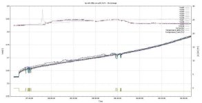
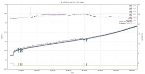
This graph for example shows the very first slow 1A charge of the freshly linked pack, where the contacts were still uncleaned (!) :
4pNIBsChargeUncleaned_s.JPG
4pNIBsChargeUncleaned.JPG


(There are some current interruptions so that one can see the absolute voltage sags/resistances of the cells.)
During the charge at the beginning I made forced mini-movements on the NIB contacts . The positive NIB contacts are on cell(array) #3, thus you see the rather huge variance pattern of the blue "Vcell3" curve - some 10mV variance - while the other cell voltages remain equal within a 5mV band. This means some 10mV/0.25A = 40mOhm per positive terminal contact - uncleaned! The constant situation after 8:45 which seems better (R_contact ~ 10mOhm constant) is yet a rather random optimum found "trial and error" by lateral shifts (watching with voltmeter on each contact), thus the situation is unreliably random without the extended treatment.

After the full contact surface treatment and oxygen stop with Vaseline now there is no more noticeable voltage variance pattern on cells #3. Only a little higher constant resistance. And important: its rather reliable - not a fragile random optimum.

Meanwhile I made 3 bike tours with that pack, using this pack in parallel with another pack to have some 800Wh. One was a day tour with 130km and all kinds of paths, consuming some 80% of total battery capacity. Its well stable according to the measurements. Measuring the contacts individually and precisely after use (avoiding shifts while unpacking), I found repeatedly that the contacts had even a little lower resistance - with exception of 2 negative terminal contacts which I did not threat extended: here resistance increased a little (and may get a lot worse over time).
On the positive terminals I got ~2.6mOhm average after that "self-improvement". And 1.0mOhm on the 2 extra treated negative terminals. So it seems that micro-movements and/or peak currents support in working the contact materials even better together - without converse effects when fully cleaned/deox'ed and when oxygen is kept away.
So after all it feels well ok for long term observations ...

Mechancial stability: I did not feel any potential trouble regarding the mechanics of the NIB contacts - though I did not position things overly exact - it all feels rather tolerant. The thin ferromagnetic nickel strips are held tough in place by the magnets - mag force quite undamped - the soldered nickel strip assembly makes things rather cohesive as a whole - could hardly be forced across the plastic barriers. The were no noticeable movements of the magnets observed when carefully unpacking things after use. The magnets are not extra fixed with glue or anything so far - perhaps I may do some tiny little drop super glue fixing when nothing changes anymore after some time, but think its not really necessary. As soon as there is soft cover material thick enough on the whole contact stuff, things are quite cohesive. >2cm wrapping stuff keeps iron things well away - there is no problem regarding with NIB pressure/position being influenced even with 3mm distance to iron tools. Yet I'll check the effects on a almost terminated bank card...
Temporarily for now while testing I'm packing/rolling the battery simply with soft packaging material tightly, 2cm or so, then hard carton, and that into a camera bag with shoulder straps, and that into the bottom of a pannier on the touring bike - luggage on top. The principle will be the same on the final package I think: cell pack - (power tape around sides) - soft stuff - tape - hard stuff - (soft bag). I don't need power tape around the cell sides here, because the cell holder is one complete rather stable piece.

Summary so far: The R_contact particularly on the positive terminals is most critical. Its not a no-brainer. Correct contact treatment and resistance checks are needed.
(@radad, I wonder if you have some measure for the situation on the positive terminals?)
After the full treatment R_contact on the positive terminals is still not completely satisfactory, but below my 5mOhm threshold (cell Rdc ~40mOhm). Without the extended surface treatment program and Vaseline, it would be rather critical and unreliable. Using more expensive N50 NIBs instead of N38 on the positive terminals could perhaps provide some factor. The 8mm NIBs cover the positive terminals rather well already, the negative terminals are significantly less critical. Perhaps 9mm or even 10mm NIBs would turn out into little more force/less resistance, but from then there is less effective overlap on the small positive area - and measurements become difficult. I don't want more than 2mm height. So perhaps N50 9mm x 2mm would be quite perfect on the positive terminals - somewhat more expensive for complete packs. But its acceptable as it is. (Usually cell Ri increases during cell aging and the effect will be higher than R_contact as of now within months I guess.)
Possible more expensive improvements which do not add geometry: silvering of contact surfaces, superconductive nanomaterial (?) ...
 
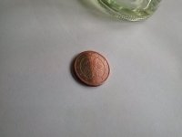
Here is a pic which shows the effects of de-oxidation on a half side of a copper coin, which is some years old. Cleaned with de-oxidative vinegar cleaner, and then cleaning the remainders with paper towel/cotton swabs and spiritus (ethanol):
coin_deox_s2.jpg

Copper quickly turns visibly dark on the surface after weeks/months/years. Within seconds thin invisible oxide layers are there. The oxide (und humidity possibly) also undermines weak force contacts easily. For an electric contact the layers first need to be penetrated by a pressure beyond a (highly variant) threshold, before the reliable linear range of contact resistance is reached. With nickel there is less oxidation/corrosion, but principally its the same. The oxide cannot be cleaned just with alcohol/tenside/soap. Unless severely scratched mechanically, de-oxidative cleaning is needed. And then further oxidation needs to be stopped by a suitable inert creme.
 
What do you think about these:

lvIDwnC.png


http://www.aliexpress.com/item/0-2mm-Pure-nickel-strip-18650-battery-nickel-plate-18650-cell-nickel-belt-Can-cooperate-with/1930319821.html

The price is a little higher then I'd like a 54 cents per unit. But that is 8 cells per two units, I just wouldn't need anywhere near 100 pieces, I would go in with someone on a lot though! ;)

I was thinking of combining these with a rectangle magnet instead, say a N45 that would span both magnets and run them over the bridging pair. *edit* This size appears to be about perfect, now to find a US vendor:

http://www.amazon.co.uk/Block-Magnets-N44SH-nickel-piece/dp/B00EE575KU
 
x-speed said:
x-speed said:
Summary so far: The R_contact particularly on the positive terminals is most critical. Its not a no-brainer. Correct contact treatment and resistance checks are needed.
(@radad, I wonder if you have some measure for the situation on the positive terminals?)
After the full treatment R_contact on the positive terminals is still not completely satisfactory, but below my 5mOhm threshold (cell Rdc ~40mOhm). Without the extended surface treatment program and Vaseline, it would be rather critical and unreliable. Using more expensive N50 NIBs instead of N38 on the positive terminals could perhaps provide some factor. The 8mm NIBs cover the positive terminals rather well already, the negative terminals are significantly less critical. Perhaps 9mm or even 10mm NIBs would turn out into little more force/less resistance, but from then there is less effective overlap on the small positive area - and measurements become difficult. I don't want more than 2mm height. So perhaps N50 9mm x 2mm would be quite perfect on the positive terminals - somewhat more expensive for complete packs. But its acceptable as it is. (Usually cell Ri increases during cell aging and the effect will be higher than R_contact as of now within months I guess.)
Possible more expensive improvements which do not add geometry: silvering of contact surfaces, superconductive nanomaterial (?) ...

Yes I have some measurements off positive. Using a known method to measure mohm (using nominal 220ohm resistor and a 5v ps yielded imprecise measurements so I doubled to 440ohm) and got the following:
1 battery, nib on + terminal, cu, nib on top of cu(.012x1x1"). Measurement from battery + to 1 inch out on cu = 1.5 mohm
1 battery, nib on + terminal, ni, nib on top of ni(.008x1x1"). Measurement from battery + to 1 inch out on ni = 6-7 mohm
So I think my test was accurate since ni requires a little over 4 times the mass of cu.
I'm seeing just a small amount better on the negatives, hard to even measure.

As for superconductors the Bucky paper won't work well with current going into the nano tubes perpendicularly. Actually not much better than cu as a conductor. Tuball holds promise though.
 
radad said:
Yes I have some measurements off positive. Using a known method to measure mohm (using nominal 220ohm resistor and a 5v ps yielded imprecise measurements so I doubled to 440ohm) and got the following:
1 battery, nib on + terminal, cu, nib on top of cu(.012x1x1"). Measurement from battery + to 1 inch out on cu = 1.5 mohm
1 battery, nib on + terminal, ni, nib on top of ni(.008x1x1"). Measurement from battery + to 1 inch out on ni = 6-7 mohm
So I think my test was accurate since ni requires a little over 4 times the mass of cu.
I'm seeing just a small amount better on the negatives, hard to even measure.

I wonder about the 220ohm/5V method, how current flows and how it works exactly - perhaps some 4-point method which goes though one cell or on 2 points of a terminal? Yet sounds like only milliamperes flowing, and with more ohms 440 it would become even less, not better - that would hardly allow to resolve milliohm contact resistances. I think the usual charge currents (1A .. 5A) which flow in the pack (devided by p number), are already rather perfect for sensing the mvolt drops directly without extra setup.

The rather tiny nickel strips 0.15mm x 5mm which you see on my photo above, have 80mOhm per meter = 0.8mOhm per cm. So _inside_ the Ni from the cell contact area to the cu-wire soldering point its only about 0.8cm or 0.64mOhm (reliable constant). Negligible vs 50mOhm cells and vs the (jittery) contact issue as it. Your thicker and wider Ni would not add 5mOhm's resistance on 1 inch - inside the Ni. Either its a contact issue (surface condition) - which is the interesting issue anyway (as it) - or there may be a measurement problem. The more stiff Ni/Steel must be (made) sufficently flat/fitting after cutting. 1.5mOhm through 2 contacts effectively (+ / ni-nib, ni-nib / cu - resistance inside cu negligible) also sounds extremely low. Surface condition?

I think with thin strips the direct contact strip-to-cell is superior, its only 1 contact, not 2 contacts plus the NIB resistance. Magnetic force is rather undamped by the thin strips. Should be so even with thin 0.15mm or 0.1mm Cu. 0.30mm is unnecessarily thick - particularly with well conductive Cu.

I don't have Cu strips so far to experiment. If you can show Cu can really make very good contact to the cells with some surface condition, e.g. even with ~8x2mm NIBs alone, or with 1cm NIBs with respect to the tick Cu, that might be interesting, though I feel 70% ok with current situation here.
I think with deox plus Vaseline/terminal grease/silicone the rather strong oxydation&corrosion of Cu can possibly be stopped. Cu is a little softer and I don't know how that turns out. But so far there are too many question marks for me what exactly is going on with the real mOhm's and surface conditions.
Silver(ing) is a known improvement for contact materials. Its soft, but also oxidizes rather likely, which is a problem with low force pressure contacts. But with ox protection ...
 
wiredsim said:
What do you think about these:
http://www.aliexpress.com/item/0-2mm-Pure-nickel-strip-18650-battery-nickel-plate-18650-cell-nickel-belt-Can-cooperate-with/1930319821.html

The price is a little higher then I'd like a 54 cents per unit. But that is 8 cells per two units, I just wouldn't need anywhere near 100 pieces, I would go in with someone on a lot though! ;)

I was thinking of combining these with a rectangle magnet instead, say a N45 that would span both magnets and run them over the bridging pair. *edit* This size appears to be about perfect, now to find a US vendor:

http://www.amazon.co.uk/Block-Magnets-N44SH-nickel-piece/dp/B00EE575KU

well the shaped Ni is rather expensive compared to cheap nickel strips (~$2 / meter). With normal strips the geometry can be easily changed - particularly with serial-first on standard cell holders.
The pro of the shaped Ni seems to be that they add to mechanical cohesion, but not really sure, things need perhaps hold together well (by tape/box pressure) _before_ such special 2D strips would add force.
0.2mm is rather thick, but may still not damp magnets too much. Yet when its rather stiff as a whole because of the thickness and of the 2D-geometry (?), I wonder if flexes well with pack bendings under the limited magnetic force. Consider there is some elevation between the cells on the cell edges - do the shaped strips have some vertical pattern therefore? - you magnet is flatt.
The thin "1D" 0.15mm standard ni strips have no problems with flexion, but I guess I would not want significantly more stiffness. (0.1mm Ni would also be ok; with Cu I'd definitely not use more than 0.1mm. link resistance is a minor vs contact resistance)

The huge bar magnets are also significantly more expensive in effect. "Axial magnetized" : don't know the effects of that in the lateral direction which you need. It seems you have then lot of magnetism going on, but only small part of it is near the hot spot pressure area. So effect on bank cards etc at some cm's distance should be take into consideration.

When build a pack from standard cell holders, I think the 3x holders make things a little more stable mechanically than 1x individual ones or 2x. The 3x ones are rather cheap on Fasttech.
 
So I received the nickel strips, I'm pleased with these so far- I may try using these with the foam pressure system as well. I ordered 8x1.5mm and 10x2mm N50s, I will be gluing these right to the strips if testing works out.

I have 2x holders, which are decent but I do get some warping which seems to straighten out once the batteries are in, but I'm thinking about moving to 3x or the 2x2 cases. These are all much cheaper on Alibaba/Aliexpress BTW.

Pictures will follow once the batteries come in.
 
Every things been going great until a recent ride showed a huge voltage drop. I disassembled the pack and tested every cell. In the last parallel positive row, the corner cell was bad, measuring .4v I'm hoping it was a factory defect. I tested all batteries as shipped @3.63v then mass group balanced them before assembly. They only had about a dozen charge cycles. Hard to believe that one cell went bad so quickly and caused an additional sag of +2v.
 
I got my second order of fasttech cells successfully.
I only got enough for a 24v pack atm so I am not in a hurry to start building my nib pack.
I did out of wonder try to spot weld a nickle strip to a nib using a dodgey spot welder setup of a 233farad 12v ultracap (normally used for kick starting ICE motors) with nails as welder electrodes.
Well I can say for this dodgey experiment that the nib most certainly didn't like the heat from the spot weld attack lost most of its magnetism instantly.
 
Heat is only made from series ? Is there solder for the sense wires with magnetic solder, so you can just stick it.
I still will just spot weld. It's a battery- lighting in a box and just pull a little when needed. Becareful, lighting
 
In the last weeks there was rather good September weather and I made several more tours with the NIB treated pack (in parallel with another pack). 3 were day tours which used >70% of capacity. Lots of bumpy paths, pack handling in trains and all.

As the checks remained good, I also used the battery meanwhile standalone for every day short city rides in the typical 2x 7 .. 15 km range - more hasty, many stop & go's - thus using full currents planned (1.2C peak) - thus risking 4x more local contact heating in case there would occur a really bad contact >50mOhm (even temporarily), which would result in >0.6W point local heat production, which could threaten the rather isolated positive cell terminals particularly which have bad heat dissipation. (sensitive sealing rings etc)

All checks remained ok so far. The contact resistances remained stable at the low values (individual measurements after use) where no changes were done: 4Negative contacts: avg 1.3mOhm / max 2.0mOhm; 3Positives: avg 2.6mOhm / max 3.2mOhm. Only 8x2mm N38 magnet strength everywhere on Ni strips. The logs also revealed no resolvable/significant temporary resistance jumps on cell groups #3 and #4 vs the non-NIB cell groups during usage.

The new cells all behaved and behave very parallel and balanced over all of the used (>80%) discharge curve so far without balancing; I switched off the balancing feature of the OZ890 BMS from the beginning to observe the pure self-discharge variances of the new cells for first. So I would clearly notice from that observation too (in addition to the resistance and temperature observations) if the NIB contacted cells in question suffer any special damage slowly sneaking in ...

---

The mentioned contact self-improvement effect took repeatedly place when starting from somewhat higher resistances after re-establishing contacts or making forced contact movements before re-packing the battery. Some effect is there which perhaps works the contacts better together by micro-movments or high currents.
On 1 positive contact yet I cleaned away the already applied Vaseline: There the resistance climbed to 6mOhm after some usages. Similar to the already mentioned former case of non-vaselined negative contacts. and similar to the case radad mentioned regarding some increase of resistance with Cu over time when I understood correctly. Thus there seems to be self-deterioration in opposite direction - there may be the positive effect (working contacts together?) as well, but surpassed by negative effects (oxidation or something else).
So there seems definitely a significant positive effect of the Vaseline even after short time and with nickel surfaces everywhere (little oxidation & galvanic effects). The Vaseline even had a sort of rather immediate effect (after seconds) during my initial experiments on the test contact. I don't have a theory for the exact cause of this - if ox-stop is really the only main issue, or some other creme/lubrication effect is there - if this happens more by mechanical micromovents or (also) by higher currents during real usage or by something else ? ... But the effect is there.

Oxygen-stop after longer time surely is critical. I watched the half de-ox'ed copper coin after 2 weeks. One can clearly see that the sparkling glance disappeared, which was there immediately after de-ox & cleaning. Deox'ed again - glance again. I started a surface comparison with Vaseline on part of the deox'ed copper.
Planned: a comparative contact experiment with copper strips under oxygen-stop. And a experiment with silvering perhaps - makes good contacts but oxidizes quickly as well. But I became a little lazy as the contact resistance goal is quite reached.

---

The banking card magnet strip survived the 3cm test (carrying battery with NIB area near the wallet). I use the chess board style alterations of magnet pole direction.
I made some rough qualitative magnet field test using the smart phone compass: When putting the compass directly near the outside of the battery bag there is hardly a effect - at least not different from a similar pack without any magnets (When putting the phone flat rather directly on top of any (ferromagnetic) 18650 cells there is a rather huge magnet effect in any case.)
A comparison with 100 pieces 8x1mm NIBs stacked all in same direction: There is a huge effect on the compass, when placing the NIB stack some 70cm away from the phone and turning the magnets: compass direction changing some 30°!

---

Summary: As of now I have a quite improved confidence in the NIB magnet contact method. After 3 weeks of rather stable situation and wary checks I'd be surprised if this doesn't work long time - when the necessary care and setup checks and some common sense are used.

* NIBs necessary for <<5mOhm cost about 30ct per cell in low order quantities. The whole setup can be re-used and enables that flexibility and easy pack maintenance.
* Price for standard strips per cell can be neglected - not different from welding/soldering.
Fresh cut strips have a strong curving at the edge - needs to be flattend of course by using flat pliers or so - quickly done.
* Material price for (sanding &) deox & cleaning & Vaseline (or similar) in order to get reliable contact resistances (in the linear force-conductivity range) is negligible. Extra piecework time per cell after learning curve: some 3 .. 10 seconds per cell.
* Cell holders/spaces cost some 10ct per cell in low order quantities - same for welding/soldering, unless one does the invalid rather dangerous assembly without any holders (strong forces on cell heads, short cuts). Holders can be reused.
* Effort for mechanical cell cohesion is not higher than for welding/soldering - at least when done correctly (Abusing welding spots, on positive terminals particularly, for mechanical cell cohesion is an invalid practice).
* Perpendicular to the primary strip direction (no matter if serial-first or parallel-first) soldering some wire perhaps is most simple and flexible. Welding also possible. Skeptical if a mere magnet solution (e.g. just ferromagnetic thin strips for parallel in serial-first assembly) is a robust thing - danger of short cuts by strip shifts/jumps. A soldered/welded P x 2 contact unit improves cohesion of the strip assembly and quite eliminates the risk of shortcuts.
This step is perhaps the most time consuming (Besides the constant outer tasks of course: BMS setup, boxing and mounting).
* No advanced precise craftsmanship is necessary so far, which would be necessary for mechanical elastic force compression methods. Constance force all the time - no matter if shocks, slight bendings, loose screws etc. The contacts are all openly accessible for resistance checks.
* There are no illegal forces on the cell heads, which could affect the sealings and cause "unexplainable" random SD deaths. The situation is even better than with semi-professional welding. The magnets do not add perpendicular forces on the sealings and will completely cancel any strong lateral leveraging forces.
* When using nickel strips, at any time the decision could be made to just weld the strips finally, which are already put in place. Just hands on.
* Problems with magnetism on outer objects (iron tools, cards, compasses, HDs ...) seem negligible - at least when using a chess board style pole alteration scheme and when some cm space is there.

Cons:
* Some effort for the learning curve and for checking resulting resistances should not be underestimated. At least in the beginning. Bad contacts must be avoided - otherwise hot spots or lethal unbalance (when no BMS is used) are a danger. Basically one needs just a normal multimeter to do the contact milliohm check: With known (charge) current I_cell per cell: R_contact=U_contact/I_cell. Costs 1 second per contact. A BMS, and particularly a BMS with logging option is of good help - not just regarding contact issues though.
 
Back
Top